CT has become a significant force in workover and decommissioning interventions over the last 15 years. According to the Intervention and Coiled Tubing Association -ICoTA- worldwide coiled-tubing rig count has increased from 1,039 in 2002 to 1,955 in 2017, the peak being 2,096 units in 2015. This means that, either by choice or by market imposition, the availability of CT units to execute interventions has doubled over the last decade.
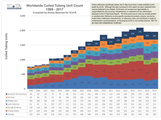
Source: Intervention & Coiled Tubing Association
Obviously, the oil price boom of 2011-14 (when the prices averaged above 100$/bbl on a regular basis) contributed significantly to attract investment in new endeavors in the industry and was an influential driver in the increase on fleet size, but that’s not the whole picture; since the 2015 peak count, despite the oil price plumbing, the units count has only reduced by 7% which is the result of the junking of old and already depreciated units that are too expensive to maintain in the current levels of profitability.
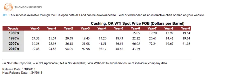
Nowadays, the price of oil is floating around 50 US$/bbl. If we look at the US Energy Information Administration’s (EIA) data (https://www.eia.gov/dnav/pet/hist/LeafHandler.ashx?n=PET&s=RWTC&f=A), we see that it was not until 2005 that prices rose and consistently stayed above the 50 US$ mark; a year with pretty much the same average price we saw in 2015.
Source: Energy Information Association
This means that we are now at market levels similar to those of 2004-2005 with a CT fleet 68% larger (1,955 units vs 1,163). So, where would the fleet size goes?
Our friends at Offshore Network wrote in their “2018 Market Forecast: What does the oil price mean for well intervention?”: “If a field is profitable in the $50 oil environment, workovers can generate a lot more value in a $60 – $70 oil environment in 2018 – alternatively, if your wells are cost negative at $50-$60 oil, it is likely they are P&A candidates as the regulatory environment will no longer allow them to be suspended until markets improve to make them economic once again”
Throughout 2017 the industry has witnessed operators moving back into healthier profits after efficiently lowering their cost base to support production operations in a $50 oil price environment. “Lower for longer” continues to be the saying from the industry gurus and VIPs in every oil conference around the world. No matter the origin of the forecast (OPEC, IEA, etc.), opinions defers to how soon the demand will catch up with the oversupply created by the U.S. shale, but nobody dare placing the Brent crude oil price above 80$ by the end of this year. That goes without mentioning that most experts see any increase above 60$ as the trigger for reactivation of those shale projects that were put on hold when prices were low, (which will then fuel back the oversupply and destroy prices again…).
In summary, Oil will remain low, leading to increased demand for workover and P&A operations. The need for adapting the cost structure and remain profitable pushes the operators towards CT interventions looking for “efficiency and effectiveness” and significant cost savings. These factors combined with the largely available CT fleet around the world present us with more and more workover programs aiming to achieve zonal isolation through CT interventions around the globe. So you better get ready to do yours with coiled tubing too!
TECHNICAL ADVANTAGES
Putting economics aside, decommissioning with CT as a deployment method also brings technical advantages, such as:
-
- Completion Left in the Well.
The CT size and its pressure control equipment allow the treatment to be performed through the completion tubulars without the need for a rig and with safe and low volume killing operation. (Instead of filling the well volume, the crew only fill the tubing and the sump (casing/hole below packer)). - Placement.
Coiled tubing avoids contamination from wellbore and displacement fluids and allows a more precise depth control. The smaller sizes minimize contamination while going downhole, and its mobile injection point also acts as a fluid displacement enhancement technique when the slurry is “spotted.” This refers to the technique of coordinating the rate at which the slurry is pumped with the speed at which the string is (simultaneously) pulled out of the hole. - Job control.
The surface equipment common to a CT spread typically provides better well data monitoring during placement and testing.
- Completion Left in the Well.
Now, to the heart of the matter: Is cementing through coiled tubing that much different from conventional plug placement methods using drill pipe and/or tubing? Short and concisely: Yes.
DESIGN
Here I’ll partner with a former colleague, Johan Bracamonte, and list for you some of the key aspects in which you should focus when designing a P&A job using cement via coiled tubing and highlight where it departs from the conventional job design.
Temperature
The relatively small flow areas and pumping rates associated with coiled tubing mean little or no cool-down of the wellbore. Therefore, one way to adjust the conditions to reflect the actual ones in the wellbore is to use the bottom hole static temperature (BHST) instead of the circulating temperature (BHCT) as recommended by API conventional testing procedures.
Rheology
Giving the small crossflow areas of a CT string and its length (which the slurry will have to go through no matter the depth of application for the plug) fluid friction is always a concern when pumping through coiled tubing. To reduce friction pressures, engineers aim at having as low viscosity cement slurries as possible. Since the cement slurries typically behave as Bingham plastic fluids, recommendations for accepted rheologies are generally given in terms of yield point and plastic viscosity. Those are:
-
- Yield Point should be from 5 lbf/100 sqft to 10 lbf/100 sqft
- Plastic Viscosity should be below 50 cP
Also, since some cementing operations may require the CT to remain inside a column of cement for an extended period, it is recommended to have no gel development within the first two hours at BHST (verifiable via rheometer tests) and also to observe linear-plateau trends in the consistency during thickening time tests. Any sign of premature gelation in consistometer graphs must be highlighted and addressed.
Free Water / Settling
CT slurries can have no settled solids or free fluid. Both phenomena could have drastic consequences for the slurry stability inside the CT reel leading to plugging of the pipe or worse. Free water tests should indicate zero, no matter the conditions. Slurry density with less than a 0.5 ppg density differential from top to bottom is considered acceptable.
Fluid Loss
Proper fluid loss is essential to ensure that the slurry will not be dehydrated in advance while pumped through the CT due to the higher pumping frictions pressures generated by the smaller cross-sectional areas of the coiled tubing. It becomes of paramount importance if the plug operation also includes a squeeze. Then the fluid loss needs to be carefully matched against the injectivity rate achieved to allow good quality cement slurry and not the slurry aqueous phase flowing through the injection point. A general rule is the lower the injectivity, the tighter (lower) the fluid loss. A general rule of thumb on fluid loss would be to keep it below the 50 cc/30 mins barrier.
Thickening Time
Since the consequences of a premature cement set, regarding asset damage and downtime, would be significantly worse compared to a similar case using conventional tubing, the thickening time selection is usually viewed from a different perspective when designing CT cement operations. Around the world, you will find various rules of thumb, all of which summarize conservative approaches to select the right pumping time for these types of jobs. Here are some examples we have run across:
-
- Minimum 8 hrs thickening time
- At least 5 to 6 hours or 3 hours over the job placement time, whichever is longer.
- Two times the placement time plus a safety factor.
In general, we do not recommend anything below six hours as a minimum thickening time. But what is more important is that these tests are done using a test schedule as close as possible to what the job conditions will be:
-
- Condition the slurry at surface pressure and temperature (plus whatever temperature is gained as result of mixing equipment shearing) for whatever amount of time it would take to batch mix the cement
- Calculate placement with the lowest possible pumping rate to be expected giving the job parameters
- Make sure heating ramp goes to BHST
- Provide at least a couple of hours safety time.
The likelihood of contamination is negligible in CT cement operations. Also, the margin of error establishing the downhole temperature base on the BHST is minimal as the amount of cooling also is negligible. Therefore, the operation after the cement is set, can be planned with very close precision assuming Waiting-on-cement (WOC) as defined by the compressive strength development charts of the non-contaminated slurry. So, whatever safety margin is imposed on pumpability will not have significant detrimental effects on any other job aspects. Hence, it’s better to be safe than sorry and choose a lengthy thickening time.
Slurry mixing
To ensure homogenous slurry properties (density, additives dispersion, etc.), the cement slurry should be batch mixed whenever possible.
Several of the general rules from our ‘ Guidelines to Set Cement Plugs‘ (if you have not read it yet, I suggest you download it at this point), still applies during CT deployments:
-
- You still need to look at the properties of your well fluid and pre/post flushes and adjust them accordingly.
- You still need a rigid base to place the plug and avoid the slurry from falling into the wellbore below by the effect of gravity. However, the spotting technique mentioned above helps in minimizing the impact of the “jetting effect” and gives less significance to the viscous pill.
These recommendations for conventional operations lack or lose validity in CT applications:
-
- The 500 ft rule of thumb don’t apply anymore, as this length accounts for contaminated cement on top and bottom, which will be smaller in CT deployments. CT could accommodate smaller plugs.
- CT is the slimmest assembly that one could find; the disturbance created by the CT while POOH inside the cement plug is negligible. However, POOH speed matching pump rates during the spotting techniques must be observed. Spotting allows plugs longer than 500 ft to be placed at one run.
Now, coiled tubing cementing is a topic on its own that deserves additional attention, and we have gone way over the maximum number of lines we want in a single article. For my next contribution to the blog I’ll partner with a known guru in CT field operations and have a look at CT applications for well integrity (Squeezes and Plugs) from a tubber’s view.
See you soon!


Miguel Diaz is Wellcem’s Business Development Manager for the Middle East and North Africa region. He has 20 years’ experience from operations, technical advisor, quality assurance, business development and management positions in the oil & gas industry from all areas of the high-pressure pumping services. Johan Bracamonte has over 16 years combined in operational, technical, training, sales and management experience in the oil & gas industry in Venezuela, US, Argentina, Bolivia, Chile & Saudi Arabia.