By Simon Sparke – International Well Integrity
‘If you don’t monitor it you can’t measure it’, while this is probably fully understood, what is missing is ‘ensuring your measurement equipment is properly calibrated’, as a measurement is meaningless if the equipment response cannot be relied upon. As well integrity engineers, we need ONE source of truth and this must be reliable, repeatable and transparent.
Technology advances but are we missing something? In this digital age there seems to be less overall adherence to this critical task of calibration of downhole tools, even to the point where I have been told it was not necessary as the tool is self-calibrating which has the same amusement levels being told that gas wells have a bubble point.
Calibration is the act of comparing a device under test of an unknown value with a reference standard of a known value and in so doing, provides us with the means to determine the error or verify the accuracy of the device under test.
As well integrity engineers, one of our concerns is the status of the well tubulars through the field life, so that we need to understand the sources or causes of sustained annulus pressure and the location(s) of metal loss over and above that of allowable metal loss during manufacture. The change in wall thickness will help determine the MAASP or MAWOP and how this impacts the well operating status.
I use the phrase ‘metal loss’ as this is important. Pipe wall thickness variations occur for several reasons; manufacturing tolerance, wear caused by interventions, erosion, and corrosion. These various attributes need to be understood by any analyst including the logging company and form part of a rational discussion about well status and the causes for change.
A range of tools are available to help determine remaining wall thickness in our well tubulars. These include -:
· The multi fingered caliper measures the internal status of a single tubular; recording metal loss due to corrosion but also recording wall thickness gains such as scale(s), paraffins and asphaltenes.
· Electro magnetics, can make measurements of multiple tubular strings in a single logging pass and these tools are NOT influenced by scale, paraffin or asphaltenes
· Sonic based tools can measure wall thickness and surface tubular status but can only record a single string and require a liquid filled environment
· Cameras now provide a comprehensive ‘view’ of the tubular and the associated completion jewellery but can only measure a single tubular string.
How do we move forward and who or what do we believe? As well integrity requires rigorous charted, signed and witnessed pressure tests on much of our pressure control equipment, then surely it is correct for logging tools etc to be subject to a similar test(s) in order to qualify their effective readings, especially as the results could have an impact on well integrity and the safety of our colleagues. The data required should include; pipe size(s), weight, wall thickness and metal grade. It should be signed and dated. Review this calibration before logging starts and ensure it passes the ‘sniff test’. Therefore, if the service provider cannot or will not support their reports with repeatable calibration data, we must question their standards.
What must be used are the allowable wall thickness variations in the tubular manufacturing process. Two key documents are available; API-5CT for regular tubing and casing (OCTG) provides for a variation in wall thickness of -12.5%
API-5CRA for corrosion resistant alloy tubulars provides for a variation in wall thickness of -10.0% OR -12.5% which is driven by the heat treatment process.
To piece all this together and provide a meaningful result, several elements are needed. These include; logging results, API wall thickness tolerance, completion design + the well production characteristics + well history and a degree of common sense. However, and most crucially, calibration data is very important.
The pictures below show tools to measure metal loss in multiple tubing/casing strings. Operators use this data to determine well status, re-calculate MAASP and if/when a workover might be required to replace strings.

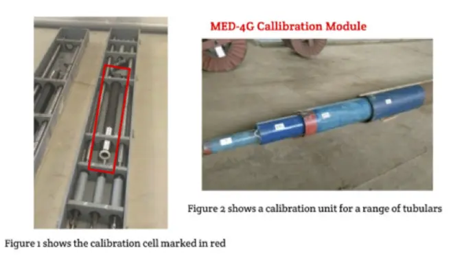
Setting a good industry example. My belief is that we should have similarly high expectations of service providers and they should demonstrate tool calibration as shown in the picture below. This company, Ginnovo, sends tools to the wellsite complete with a calibration cell. This provides the opportunity to confirm the accuracy of the collected data, while still in the field. It withstands scrutiny and demonstrates the appropriate level of professionalism that we as responsible companies should demand. If they can’t deliver, then my recommendation is to seek alternative providers and in this field there are several.


