HydraWell has joined forces with READ (including subsidiaries READ Cased Hole and ANSA), a cased hole production logging, well integrity and reservoir evaluation solutions provider, to create a leading well integrity specialist with ambitions to play a prominent role in late-life oilfield activities.
Both companies have long-established histories of delivering expert well integrity services and solutions for clients around the world. The new combined company will be strategically located with offices and bases in Stavanger, Aberdeen and Houston together with a presence in Alaska, Australia, Brazil, Malaysia and Qatar. HydraWell CEO, Mark Sørheim, will now be CEO of the combined company which will have a total of 75 employees. Total revenue for the combined company is expected to reach approximately US$20.3mn in 2022.
According to HydraWell, late-life oil and gas wells worldwide have an increased requirement for well integrity monitoring, and there is a growing demand for permanent plugging and abandonment of these ageing assets. HydraWell, READ and ANSA will operate within well integrity, with READ and ANSA measuring and analysing well integrity issues with HydraWell remediating the issues identified. The combination of the companies will allow customers to benefit from seamless well integrity planning and diagnostics to barrier installation using digital tools, repeatable and reliable service delivery and effective new technologies that reduce risk and cost to operations.
Sørheim commented, “This is an exciting juncture in our corporate journeys, and we are delighted to join forces with a like-minded specialist business whose services are complementary. This allows us to create a unique offering within the well integrity market to deliver further added value to our customers through deeper knowledge, increased operating efficiencies and improved workflows across their well operations.”
Manager Director of READ Cased Hole, Bruce Melvin added, “READ Cased Hole continues to go from strength to strength and the merger adds to this by positioning our new entity as leading integrated well integrity measurement, analysis and remediation specialists. This will not only enhance READ’s presence in the abandonments market but also expedite ANSA’s digital platform attracting new client relationships. We look forward to what the future holds and building on the success of both companies.”
Archer Oiltools has been awarded a two-year contract extension from Equinor Energy AS in the North Sea.
The contract covers plug and abandonment (P&A), fishing and downhole mechanical isolation equipment. Based on current activity levels, the additional backlog is estimated at US$60mn for the 24 months period which will commence in June this year.
“This is a strategically important extension for Oiltools in one of our core markets, which further strengthens our footprint and presence in the region. Our technology and strong record of execution in the North Sea makes us a supplier of choice for Equinor. We continue to support Equinor’s requirements for safe and efficient operations while providing proprietary low carbon solutions and operational efficiencies to further their energy transition goals,” said Hugo Idsøe, Vice President, Archer Oiltools.
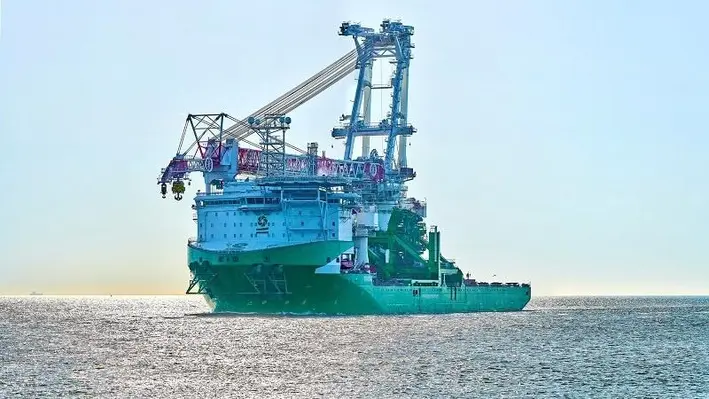
Liebherr has announced that its Heavy Lift Crane (HLC) 295000 is on board the Orion and is ready to work on decommissioning projects.
The Orion is a next generation offshore installation vessel by DEME which is capable of installing windfarms and decommissioning ‘old’ energy platforms. On the vessel, Liebherr has delivered the HLC which is the largest crane the company has ever built, boasting a lifting capacity of 5,000 tonnes.
After its name-giving ceremony in Vlissingen, Netherlands, the vessel is now heading to help develop the offshore wind farm ‘Arcadis Ost I’ in the Baltic Sea.
“What we are witnessing here, is indeed a very memorable event. Fundamentally, it demonstrates what is achieved, when people are closely working together, especially alongside with a competent and reliable partner. Today, we are proud. In an extraordinary effort, our team at Liebherr brought this heavy lift crane up on this ship so now everyone can see what has been accomplished,” said Robert Pitschmann, Global Application Manager, Heavy Lift Offshore at Liebherr.
By the help of the compact design, the crane is destined to serve in the offshore market. For example the base column, being only 16.8 metres diameter, is unique in the market. The HLC 295000 requires little space on deck and offers more storage space for transportation. It is ready to take up its work in the ample field of the offshore industry. With its maximum capacity of 5,000 tons and an outreach of up to 151 metres, the HLC can manage large components, for example, during the decommissioning of offshore platforms.
A maximum lifting height of 175 metres enables the HLC 295000 to operate in the required height right away without special efforts. All this demonstrates that the heavy lift crane in general can be regarded as the ideal instrument for the challenges ahead within the changing field of energy production as well as in all related working areas closely related to it. The extraordinary efficiency, swift- and readiness when it comes to transporting, accuracy but also power give this Liebherr heavy lift crane and the HLC-Series an advancement due to its smart versatility.
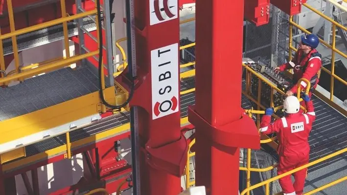
Northumberland-based offshore technology company Osbit has announced that it is set to receive a Queen’s Award for Enterprise.
Osbit has been rewarded for its excellence in innovation – a nod to outstanding achievement and commercial success.
The prize has been given to the company for its development of offshore technology to deliver a step-change in offshore operations. Osbit’s Intervention tension Frame system were designed for industry-leading services company Helix Energy Solutions and use innovation to support energy transition activities, facilitating safer and more efficient closure of expired oil wells.
A representative from Osbit will collect the award at a reception hosted by HRH The Prince of Wales at Buckingham Palace, in July.
Director Steve Binney, commented, “This win is fantastic recognition of what Osbit is capable of, in terms of developing large and complex systems, successfully delivering them, and making a real difference to our customers’ project outcomes.
“Innovation has always been at the heart of everything we do – we’re constantly trying to use our engineering skills to improve on what’s gone before, to do things better, more safely, more effectively.
“We are very proud of this win, which is testament to the genuine skill and ingenuity of our team.”
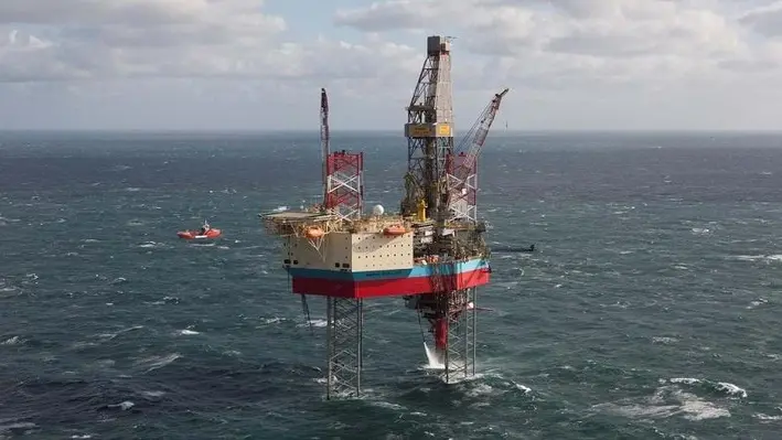
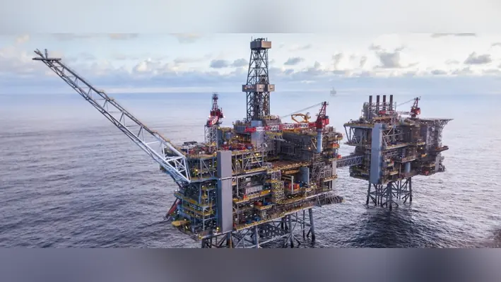
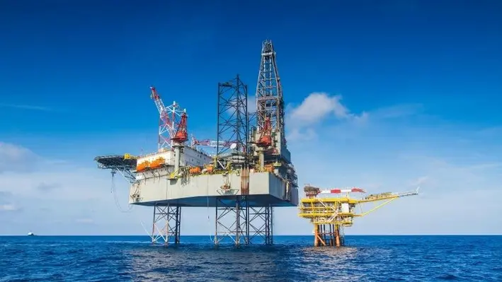
Maersk Drilling has been awarded contracts which will see the harsh environment jack-up rig Maersk Resolute, employed to plug and abandon (P&A) a total of 31 wells in the Dutch sector of the North Sea.
Maersk Resolute is a 350ft Gusto-engineered MSC CJ50 and a high-efficiency jack-up rig that was delivered in 2008, currently operating offshore the Netherlands.
The newly-awarded contracts, which are expected to commence in Q2 or Q3 of 2022, are in support of a rig sharing agreement between TotalEnergies EP Nederland BV and Petrogas E&P Netherlands BV. They are in direct continuation of the rig’s current contract, and will include the plugging and abandonment of 11 wells with TotalEnergies and 20 wells with Petrogas.
The estimated duration for the substantial campaign is 575 days, and the total firm contract value is approximately US$43mn, excluding potential performance bonuses. The contracts include options to add additional work scopes with a total estimated duration of 228 days.
COO Morten Kelstrup of Maersk Drilling, commented, “We’re pleased to secure this long-term commitment for Maersk Resolute to continue operating in the Netherlands. By deploying the rig for a combined 31-well campaign we will be able to ensure a consistent focus on efficiency improvements from well to well, while simultaneously operating with the respect for the continued sustainability of the marine environment that is a key component in successful plugging and abandonment operations.”

DOF Subsea has attained a 99% rate for the combined recycling and repurposing of recovered materials on its decommissioning project for Repsol Sinopec Resources UK.
The company provides engineering, preparation, removal and disposal (EPRD) services at the Buchan and Hannay fields in the Central North Sea.
The offshore works were carried out for over 74 days, using Skandi Acergy and Skandi Skansen, and saw the recovery of 135 concrete mattresses weighing approximately 800 tonnes, more than 12km of rigid pipelines, SSIV/PLEM Structures, 15.5km of flexibles and umbilicals, spoolpieces, and around 1,500 grout bags and general debris.
The material was shipped to Aberdeen Harbour’s Clipper Quay for dispersal, with the recovered material dispatched for a wide variety of uses. A total of 15 concrete mattresses were repurposed into aggregate for use in the roads at the £350mn Aberdeen Harbour extension project. The plastic sheaths from the flexible risers and umbilicals were recycled by an approved supplier and all metal was smelted.
This was the second decommissioning project carried out by DOF Subsea on behalf of Repsol Sinopec in the Buchan and Hannay fields. In 2019, they carried out EPRD services, including the 124 tonne Mid-Water Arch (MWA) – one of the largest structures ever decommissioned through Aberdeen Harbour.
DOF Subsea has built a decommissioning portfolio over the last decade, delivering more than 30 projects around the world for major operators.
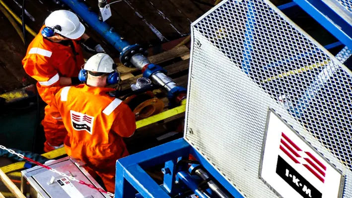
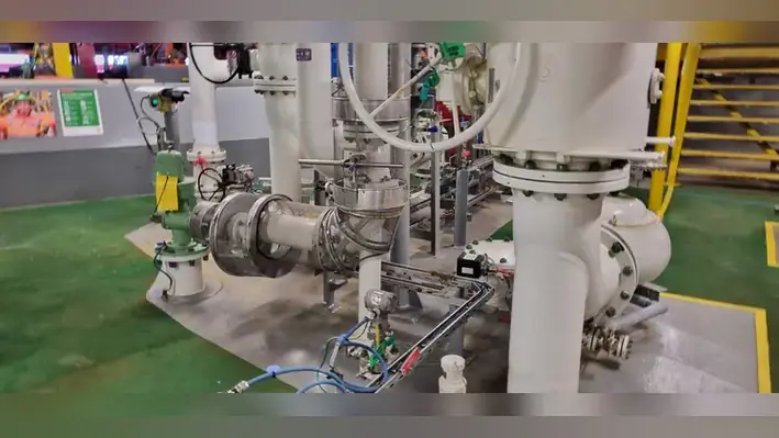
IKM Testing UK, an independent integrated solutions provider, has been awarded a multi-year contract to deliver well integrity services across bp’s portfolio of North Sea assets.
The agreement – the first well services contract between the companies – comprises well integrity remediation services, which includes sustained casing pressure mitigation (SCP).
SCP is excessive pressure in any well annulus that requires regular bleed down and often can be managed during normal offshore operations, depending on the severity. It also requires remediation during P&A operations if not addressed during the normal well lifecycle.
This new contract looks to address the issue of SCP in a more permanent manner, reducing the requirement for continual management. Under the contract IKM will provide engineering, determination of applicable chemistry/methodology, and deployment of equipment and personnel offshore.
Work to remediate sustained casing pressure using a bespoke resin capable of being placed via gravity feed is expected to commence in 2022.
Mark Rasmusen, Director of International Division at IKM Testing commented, “This is an exciting award and provides the springboard for us to further grow and develop our well services offering.
“Sustained casing pressure can generally be managed offshore, however bp is looking for a solution that doesn’t require continual management by offshore personnel which not only reduces risk but also saves significant time and costs. We were selected as we provide an independent perspective and have the capabilities to carry out the full suite of engineering services from cradle to grave.
“We look forward to helping bp achieve its well integrity goals by determining and executing innovative and cutting-edge solutions.”
The contract also has future provision for supporting bp’s international assets with similar workscopes.
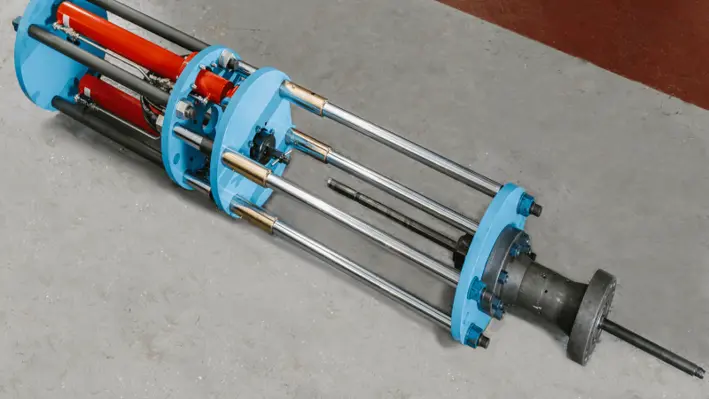
HydraWell, a well solutions provider based in Norway, has recently introduced its innovative downhole tooling solution ‘HydraTyphon’, to deliver improved reliability in difficult environments.
According to HydraWell, the solution combines the benefits of jet and cup-based washing and cementing systems, and has been designed to improve the efficiency of the downhole hydraulic activity over any other system available. The combined advantage of these two systems is said to reduce perforating and operating costs as well as minimise environmental impact.
Tom Leeson, Chief Commercial Officer at HydraWell said, "Our experienced team is focused on developing ingenious technologies to transform well operations around the world. We are always looking for ways to push the boundaries and HydraTyphon hits the mark for new advancements in downhole tooling techniques. HydraTyphon offers a wide range of benefits, not least providing our clients with the chance to reduce their environmental footprint whilst transforming their well operations.”
Back in 2008, HydraWell designed, developed, tested and patented a system portfolio for wellbore applications known industry-wide as Perforation, Wash and Cement (PWC). The company says its PWC technology has the potential to slash the operational sequence by up to six days when compared to the conventional section milling alternative. The increased efficiency benefits help to reduce environmental impact as well as the potential to reduce operating costs by up to millions of dollars in estimation.
HydraTyphon is an evolution of PWC delivering improved reliability for challenging well characteristics including high cement content in annuli, shallow barrier depth and large annuli.
Mark Sorheim, CEO at HydraWell commented, “We pride ourselves on being true innovators – our forward-thinking team continually develop our range of systems in response to bespoke customer requirements to support industry challenges. Furthermore, HydraWell regards sustainability as one of its top priorities as we strive for efficiency gains and proactively lower the risk of long-term environmental damage by exploring and developing solutions to support our clients’ environmental savings.”
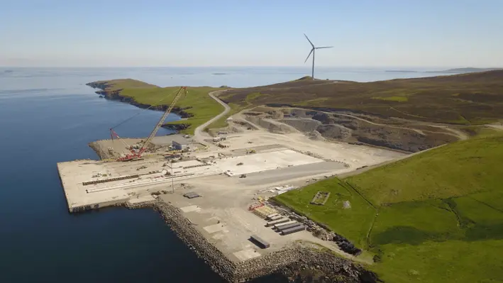
Following the award of another major North Sea contract to Veolia and Peterson, Lerwick Harbour will be the location for the dismantling and recycling of a northern North Sea platform jacket.
This follows the winning of the contract to decommission the 14,500 tonne topside for the same platform, which will be the biggest to date at the port’s Dales Voe Base. This was recently completed on time with Veolia and Peterson achieving their target of more than 98% of materials recycled.
The latest project has been awarded by Allseas and is for the 83-metre steel jacket which weighs in at around 8,500 tonnes. This will also be delivered by Allseas Pioneering Spirit.
Preparations are now underway for the reception of the jacket. Similar to the topside, it will be removed in a single lift before being transferred ashore at the base via a barge. A heavy-duty purpose-built decommissioning pad will be used.
John Abraham, COO of Veolia UK & Ireland – Industrial, Water & Energy, commented, “Industry leading recycling involves innovation and scrupulous planning. With our major complex decommissioning projects, we have already shown that it is possible to achieve a 98% recycling rate for obsolete oil and gas structures, a key achievement as we look to preserve resources and drive our ecological transformation. Decommissioning is also very important from a carbon perspective as recycling a tonne of steel saves 1.5 tonnes of iron ore and reduces CO2 emissions by 80%, compared to metal production from raw materials."
James Johnson, Decommissioning Manager at Peterson, remarked, “We believe this award demonstrates the strong track record of Peterson and Veolia in handling all types of offshore decommissioning projects, as well as the excellent capability of the Dales Voe Base. It is also recognition of the excellent work undertaken in the decommissioning of the Ninian Northern topside, where an industry first approach to decommissioning an offshore asset proved very successful. We are very pleased that the award will also help secure a number of Peterson roles on Shetland on an ongoing basis.”
The jacket is expected to arrive in April 2022 with decommissioning taking around eight months to complete from this point.
Expro, a provider of energy services, has acquired 100% of Distributed Fiber Optic Sensing (DFOS) company, SolaSense Ltd.
Based in the UK, SolaSense’s well surveillance technology features portable processing software and an enhanced visualisation interface for delivering near-real-time analysis of distributed acoustic sensing (DAS) / distributed temperature sensing (DTS) data at the well site. This allows well characteristics to be readily recognised and evaluated, avoiding the shut-in of wells for extended periods and minimising lost production.
This acquisition along with Expro’s 50 years of well intervention and integrity experience, will allow the company to meet industry demand to provide customers with a one-stop-shop service for the in-depth evaluation of the entire well and also the provision of any subsequent remediation solutions. Expro’s DFOS offering monitors dynamic behaviour in the well, providing a health check of the well and an accurate diagnosis of any well and reservoir issues.
Compared to traditional completion deployed applications of fibre optic technologies, DFOS can be deployed thru-tubing and used to analyse and evaluate well performance and integrity within hours of the completion of the survey providing greater insight into the dynamic behaviour of the well, to help customers make important time-sensitive decisions. Supported by DFOS, it can provide an enhanced cased hole offering integrated slickline mechanical services all within Expro.
Steve Russell, Expro’s Chief Technology Officer, commented, “We are committed to delivering cost-effective, innovative technologies and solutions, and best-in-class safety and service quality performance to our customers, all while advancing our commitment to creating a more sustainable business and lower carbon future.
“Access to representative well data is key for making informed well performance and integrity decisions. This acquisition allows us to build on our existing well intervention and integrity portfolio, leveraging the expertise from both companies to extend our customer’s wells’ lifespan, while reducing time and costs. Led by a highly skilled and dedicated team with extensive industry experience, we look forward to building on our digital solutions and welcoming the SolaSense team to the Expro family,” he added.
John Davies, SolaSense CEO, said, “The SolaSense ambition has always been to see distributed fibre optic logging being used widely as a simple and affordable means of well performance and well integrity monitoring. The integration of SolaSense’s technology and expertise into Expro’s existing global well intervention footprint will fast track the realisation of this ambition, and more importantly, add value for the end customers through the wider uptake of fiber-enabled slickline deployed DFOS surveys. The SolaSense team are very excited about this significant development and look forward to supporting Expro in the fast and efficient expansion of DFOS well logging.”
Unity, a provider of well integrity solutions, are supporting a North Sea well decommissioning programme for a major international operator, using its multifunctional Surface Intervention System (SIS).
The SIS has already completed intervention work on the first well, where it was deployed offline to set a shallow bridge plug in preparation for the removal of wellhead equipment. Unity’s standalone technology replaced the need for traditional intervention equipment. It delivered considerable savings to the operator in cost, time and efficiency, by working below deck while plug and abandonment (P&A) drilling operations were ongoing. Compared to traditional methods, the intervention was performed around 60% faster and delivered a cost and personnel package saving of 66%.
During the project, deck space and bed space were limited due to drilling operations, but Unity’s compact SIS technology, which requires just two technicians to operate, provided the ideal shallow intervention solution. The SIS was also said to be easy to accommodate on the platform below the drilling rig in a restricted well bay. The SIS and pressure control package were rigged-up below deck using a small A-frame crane provided by Unity. The plug was set first time and the equipment was rigged down within 24 hours.
Gary Smart, CEO at Unity said, “The SIS has great utility and has been by used several operators for milling, inspection, fracturing and P&A operations, enabling material savings against traditional shallow well intervention techniques. This technology will soon be joining our newly-announced Compact Shear Seal Valve technology, reducing the footprint and weight of the overall system even further.”
The SIS is the first multifunctional shallow well intervention system on the market and combines heavyweight capability within a compact and mobile package. The SIS has a powerful hydraulic motor, driving a push, pull and rotate function which can rival wireline or coiled tubing capability.
Unity has established an impressive well decommissioning project track record which currently extends to over 150 wells with another 230 in the pipeline over the next three years.

Spirit Energy Production UK Ltd. has awarded Heerema Marine Contractors a contract for removal and disposal services of the operator’s North Sea decommissioning portfolio.
The EPRD (engineering, preparations, removal, and disposal) contract includes both firm work and optional scope that can be called-off by the client. Heerema Marine Contractors will lead its part of the work out of its offices in Leiden (NL) and London (UK). Heerema will cooperate with DeepOcean, the subsea asset removal contractor, to deliver the safe and sustainable decommissioning of the platforms.
The firm scope involves the EPRD of the Audrey A, Audrey B and Ensign platforms, while the optional work includes an additional five platforms in the southern North Sea region of the UK and Dutch sectors.
Following a joint tender submitted in cooperation with DeepOcean Subsea Services Limited, both firms have secured contracts that will be executed under a tripartite collaboration agreement.
Heerema’s scope is to remove and recycle the platform topsides and substructures, while DeepOcean will be responsible for removing and recycling all subsea assets at the relevant fields. The combined weight of the firm scope topsides and jackets is around 7000 metric tons, and will be recycled in the UK. The platforms are located between 23-26 metres of water.
Heerema’s Decommissioning Director, Michel Hendriks, commented, “Decommissioning North Sea platforms is an important component within Heerema’s portfolio, and we are proud to be Spirit Energy’s chosen contractor for the topside and substructure scope. We are also looking forward to working alongside DeepOcean and their team to deliver the safe and sustainable removal of the Audrey A, Audrey B, and Ensign platforms.”
Copyright © 2026 Offshore Network