C-Innovation (C-I), an affiliate of Edison Chouest Offshore (ECO) and its family of companies, has announced the completion of its 46th well intervention in the Gulf of Mexico.
C-I, a leader in providing turnkey intervention services for the global subsea industry, also successfully completed three new riserless zone perforations, an industry first in both deepwater and high-pressure operations. The well intervention programme provides increased efficiency along with faster response times for emergent situations through the quick mobilisation and deployment of a vessel. C-I specialises in downhole operations, including production injection and integrity logging, caliper measurements, and setting water shut-off and zone bypass plugs. With more well intervention operations planned for 2023, C-I has played a pivotal role in increasing output for operators in the Gulf of Mexico.
George Wilson, Riserless Light Well Intervention Project Manager, C-I, said, “We are very proud to be a part of increasing oil production in this challenging geo-political climate. Riserless interventions on vessels offer both time and cost advantages over riser interventions. C-I’s programme offers the added benefit of dedicated dock space with advanced fluid tracking for faster between-well maintenance.”
C-I’s well intervention programme, which made its debut in 2017, has performed 31 hydraulic interventions and 15 mechanical interventions. The mechanical interventions included a total of 85 successful wireline runs, both e-line and slickline. C-I recently completed its longest mechanical intervention on board the vessel, Island Venture. With 79 days offshore, the operation included 22 e-line and slickline runs, as well as 22,205 barrels of fluid pumped into the well.
Wilson added, “C-I is a fully integrated service provider for our clients. Our turnkey solutions for well interventions alleviate the hassle of coordinating and managing the multitude of subcontractors needed to address complex jobs."

Researchers at the University of California, Davis, have suggested the cost of permanently plugging and abandoning the inactive oil and gas wells across the waters near Alabama, Louisiana and Texas could be upwards of US$30bn.
A paper released in the Nature Energy journal stated the area is home to 14,000 inactive wells that have not produced for five years and are unlikely to be reactivated in the region that has become the epicentre of US offshore oil and gas operations.
Leaks from wells closer to shore are more likely to damage ecosystems and release GHG emissions compared to deepwater wells. Studies have found that more than 90% of inactive wells are in shallow waters, and the costs to perform P&A services on those alone would be US$7.6bn.
The findings could help states makes decisions regarding their clean-up priorities, especially as US$4.7bn in federal funding has been authorised by the Infrastructure Investment and Jobs Act.
Liability falls to prior owners to plug and abandon wells in federal waters if the current owners become insolvent and are unable to cover costs. Large US oil companies currently own or have previously owned 88% of the wells in federal Gulf of Mexico waters and would legally shoulder the P&A liabilities.
However, in individual state waters, each jurisdiction handles liability differently, and prior ownership isn’t relevant. States oversee plugging programmes for orphaned wells whose owners have claimed bankruptcy.
“The bulk of the cost comes from plugging wells in deeper water where the environmental consequences are less than for shallow wells closer to shore,” said Mark Agerton, an Assistant Professor at UC Davis and lead author of the paper published.
“That money is probably better spent on state waters where they can’t go after prior owners for clean-up costs and it’s going to be a cheaper clean-up job with more environmental benefit.”
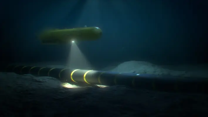
Nauticus Robotics, a developer of autonomous robots using artificial intelligence (AI) for data collection and intervention services, has been awarded a US$2.7mn contract extension with Leidos Holdings.
The extension allows for the continued development of Aquanaut-derivative in preparation for customer adoption decisions and government opportunities expected this year.
The subsea platform is an unmanned underwater vehicle (UAV) with advanced AI and sensing capabilities. It can perform a growing number of jobs without posing a hazard to human divers. The programme has now received US$14.5mn from Leidos since 2022 and the technology is expected to underpin major future opportunities.
Like the Aquanaut, the derivative robot features technology to support security activities and is advancing to complete more challenging missions. The award allows further autonomous behaviour and operational capability enhancements to toolkit, Nauticus’ proprietary software package developed to enable an ecosystem of autonomous actions for subsea vehicles and services as the foundation for this work.
Nicolaus Radford, founder and CEO of Nauticus, commented, "I am very proud of our team's performance resulting in this follow on award, further cementing our partnership with Leidos. This very important work combines great attributes from each company to deploy a truly novel subsea capability."
ABB, a technology leader in electrification and automation, has highlighted how its emissions monitoring technology is now employed to identify and monitor orphan wells in the United States.
With the help of ABB technology, organisations such as The Well Done Foundation, the nonprofit organisation that works to plug orphan oil and gas wells in the country, can detect leaking wells and, once the wells are capped, continue to monitor the sites to ensure they no longer emit harmful greenhouse gases.
The United States Environmental Protection Agency estimates that methane emissions from over two million inactive, unplugged wells, of which orphan wells are a subset, range from a CO2 equivalent of 7 to 20 million metric tons per year (approximately the emissions of two to five million cars). Methane has more than 80 times the warming power of carbon dioxide over the first 20 years after it reaches the atmosphere, according to the Environment Defense Fund.
“It is extremely rewarding to see our technologies employed in the endeavor of fixing such a pressing environmental problem. We remain focused on accelerating the pace of environmental programmes that reduce emissions, especially in the oil and gas industry. Our work on this initiative is a great example of how technology can benefit the environment and help countries achieve their sustainability goals,” sayid Jacques Mulbert, Division President, ABB Measurement & Analytics.
Together with channel partner Winn-Marion, ABB worked to create a comprehensive approach that enables the identification, on-site qualification, and monitoring of orphan wells.
Initially, ABB’s gas leak detection system is used to find the orphan wells. Depending on their location, the high sensitivity analysers using OA-ICOS technology are transported by vehicle (using ABB Ability MobileGuard), drone (HoverGuard), or backpack (MicroGuard) to the site. The system can detect methane emissions down to one part per billion (ppb).
Once on-site, it measures methane concentration and flow with a measuring range as low as 180kg/h. The flow from the thermal mass is logged and visualised on ABB’s gas flow computers, the control devices known in the industry for their extreme accuracy and reliability. In the post-plugging phase, methane emissions continue to be monitored.
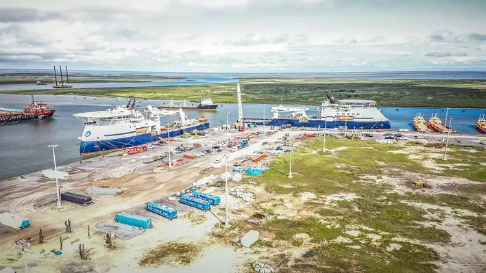
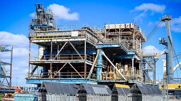
C-Innovation LLC (C-I), and affiliate of Edison Chouest Offshore (ECO), has expanded into a new facility in Port Fourchon, Louisiana, which will provide an additional dock for subsea inspection maintenance and repair (IMR) and riserless light well intervention (RLWI) services.
The dedicated docks, along with C-I’s current location, will provide the company’s clients with faster mobilisation, demobilisation and maintenance times, equating to cost savings.
The secondary location will offer vessel loading, project system integration testing (SIT), and mobilisation and demobilisation services for the subsea market. Delivering C-I’s premier customer service, the facility provides 24/7 operations, dedicated dispatcher support, a weekday manager, and client offices with conference rooms to be constructed later in the year.
JeanPaul Guidry, Shorebase Operations Manager, C-Innovations, said, “The new facility serves as a hub for executing all of our subsea projects. As C-I’s projects move from the initiation and planning phases, our shorebase operation facilities provide an efficient workflow as we move projects into mobilisation and execution.”
For IMR work, C-I provides both short and long-term storage for project equipment, and can move into SIT prior to mobilisation. For RLWI services, equipment and fluid can be staged prior to each mobilisation or between well maintenance (BWM). SIT and preventative maintenance can be completed at the new facility before the vessel is ready to start a well campaign.
Guidry commented, “Our customers trust C-Innovation with providing a turnkey project execution solution. Having facilities dedicated to project execution creates a unique offering within the subsea service provider marketplace, and helps strengthen the trust our clients have in C-Innovation.”
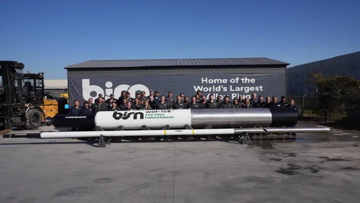
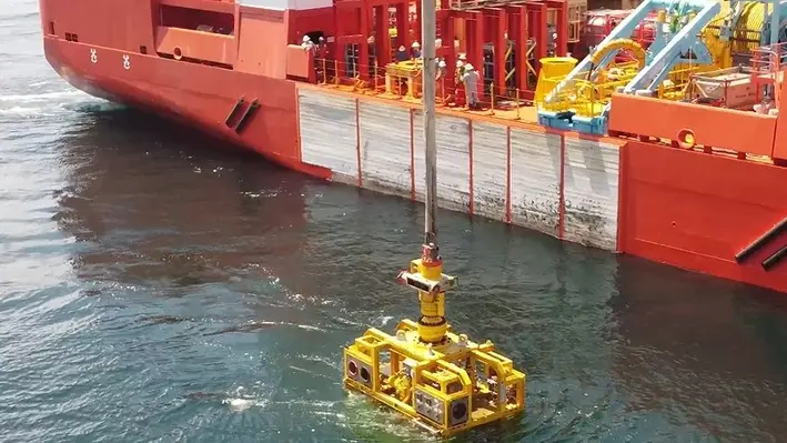
BiSN, a leading supplier of downhole sealing solutions and technology, has set a new record for the largest bismuth plug after a recent deployment in the Gulf of Mexico.
A permeant, gas-tight seal was required for a well with a 36” OD that was experiencing gas migration. To seal a well of that size, BiSN scaled its Wel-lock technology and operations to meet the needs of both the size of the tool and the production timeline requested by the operator.
As the well had already been sealed with cement but was still experiencing gas migration, BiSN needed to deploy its Wel-Lok technology without using a rig. An innovative deployment method was applied using a liftboat and remote operated vehicles (ROV) to guide the tool into place.
Once the tool was activated, the bismuth alloy flowed and solidified, filling and sealing the cross section of the conductor pipe in less than an hour.
“The success of this tool really speaks more about the flexibility and varied applications of BiSN’s Wel-lok technology, the size is just part of the story,” said Paul Carragher, CEO of BiSN.
“By utilising BiSN’s technology, we ensured a permanent seal giving the supermajor operator peace of mind, saving them time as we were able to deploy from a liftboat and costs as a rig wasn’t necessary. We have now completed over 400 deployments worldwide with BiSN’s Wel-lok technology gaining significant momentum and I’m excited as we continue to expand the range of applications for which the technology can be used, as well as BiSN facilities and people worldwide to support the growth.”

Next-generation leader in geothermal technology, Fervo Energy, has announced a US$10mn strategic investment from Devon Energy Corporation in order to initiate a partnership between the two companies and apply Devon’s 50-plus years of innovation in oil and gas to Fervo’s advanced geothermal capabilities.
Co-founder and CEO of Fervo, Tim Latimer, said, “We are thrilled to have Devon as a partner. Devon is a technology leader with historic and unparalleled expertise in drilling and completing wells. We expect this partnership will help unlock further potential for geothermal as the primary 24/7 renewable energy source.”
“We are excited about this partnership with Fervo, and innovator and leader in the enhanced geothermal space,” commented David Harris, chief corporate development officer and executive vice president, Devon.
“This investment is a good match for Devon’s new energy ventures strategy.”
Fervo applies horizontal drilling, multi-stage well completion and distributed fibre optic sensing to geothermal reservoir development, delivering higher reliability on projects. Fervo’s approach makes geothermal power accessible in far more places than before and increases its potential as a widespread energy source.

Geothermal Technologies (GTI), a company dedicated to developing clean energy, has filed for drilling permits with the Division of Water Resources in the State of Colorado, US.
GTI is seeking to drill geothermal wells for the purpose of generating utility-scale electricity in the Denver-Julesburg (D-J) Basin. GTI’s proprietary GenaSys Geothermal Energy Harvesting System ushers in the latest generation of geothermal technologies. When coupled with advanced Organic Rankine Cycle (ORC) power generation technology, GTI’s innovative system enables the efficient extraction of geothermal energy in geographic regions around the globe that have been out of reach using conventional approaches.
“This is an important step forward in our plans to construct a first-of-its-kind geothermal power plant in the D-J using GTI’s proprietary suite of technologies,” said J. Gary McDaniel, CEO of GTI. “We are excited about the potential that exists in Colorado for the development of advanced geothermal power. GTI has calculated that the thermal prospect in the DJ Basin has over 5GW of geothermal energy that can be harvested using our technology. Our field development plan for generating power indicates we can install up to 400MW of baseload electricity production.”
Jim Hollis, President and COO of GTI, added, “Our GenaSys technology promises to make geothermal baseload power both low in cost and truly scalable – locally, regionally, and globally. We plan to begin by constructing a small 5MW power plant in the D-J basin and then scale from there.”
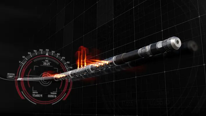
Halliburton, a leading provider of products and services to the energy industry, has announced the implementation of the Auto Pumpdown service within the company's hydraulic fracturing business which enables wireline and pump automation during unconventional completions operations.
The Auto Pumpdown service controls fluid pumps and a wireline unit as a single, fully automated, closed-loop system to maximise Halliburton’s plug and perforating performance and efficiency. The system executes operations to plan and optimises equipment operation for improved consistency.
The service enhances operations by automating tasks previously prone to human inconsistencies and reduces risk by providing prompt feedback to dynamic downhole conditions. These improved consistencies create more efficient operations and reduce required fluids for tool conveyance.
Chris Tevis, Vice President of Wireline and Perforating, Halliburton, commented, “Halliburton’s Auto Pumpdown service ushers in a new era of intelligent plug and perf operations that reduce risk while redefining the level of efficiency and consistency we provide our customers. The service reinforces our leadership in unconventional perforating services by minimising variability in operations, which helps avoid unnecessary and costly well interventions and simultaneously improves efficiencies.”
Multiple perforating crews in North America currently use Auto Pumpdown service. Here, it has demonstrated improved operating efficiencies, reduced fluid requirements, and reduced risk of unnecessary well interventions.
Halliburton will implement Auto Pumpdown service on its North America fleet through 2023 and beyond.
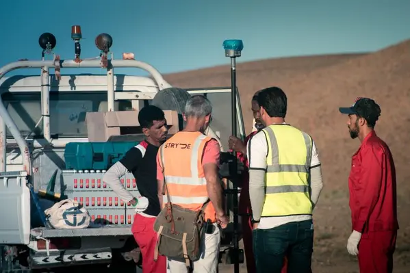
Onshore seismic acquisition and imaging experts, STRYDE, has enabled five new geothermal projects in Q1 of 2023 with the supply of its low-cost seismic technology, with a further five contracts for scheduled to commence during Q2.
The global contracts, equating to a six-figure sum, will see the company’s technology deployed across the US, Middle East and Europe.
Two of the ten contracts include nodal equipment supply and seismic data processing for STYDE’s largest geothermal project to date in the Middle East, as well as a European survey that was constructed alongside a geological research centre in Belgium. Five of the seismic surveys have already commenced, and all ten are expected to be completed by the summer of 2023.
Nick Tranter, STRYDE’s Business Development Manager for New Energy, said, “Within the renewable energy space, STRYDE presents a cost-effective and reliable solution to help geothermal operators de-risk investment decisions, with high-resolution seismic data.”
Mike Popham, STRYDE CEO, commented, “I am proud to have STRYDE play a part in supporting the energy industry transition towards net-zero. Our technology has proven to be a key tool in propelling more than 20 geothermal projects to date, by providing an economically viable solution for understanding and monitoring the subsurface.”
Razor Energy Corp. in conjunction with FutEra Power Corp. has announced the successful construction, commission and operation of its co-produced geothermal power project in Swan Hills, Alberta.
The project combines an Organic Rankine Cycle (ORC) Turbine, which captures geothermal heat from the production fluid, and a Natural Gas Turbine (NGT). Both the ORC and NGT have grid interconnections which enable direct sales of electricity to the Alberta grid, and both systems have been running in a steady state while optimisation efforts are being made in order to reach the designed capacity.
Razor produces and injects large volumes of hot production fluid on a daily basis as part of its ongoing conventional oil and gas operations, and FutEra capitalises on that by capturing the geothermal heat energy from the fluid and using it to generate power with zero greenhouse gas emissions. The co-production element of the project means there is no new surface land footprint as the project utilises existing assets such as processing infrastructure, producing wells, produced water reinjection system and an operating gathering and distribution system.
In addition, the co-production approach enables Alberta’s fledgling geothermal industry to develop alongside the powerhouse of Alberta’s world-class oil and gas operations.
Justin Reimer, CEO of Emissions Reduction Alberta, said, “Alberta has long championed the geothermal industry. It is exciting to watch an idea for a pilot project grow into an industry-scale, commercial operation. This made-in-Alberta solution ushers in a new era of clean energy that will spur an entirely new industry in the province that taps into our existing oil and gas resources and expertise.”
FutEra’s next phase of the project will see the addition of solar, and potentially carbon capture, with the objective to create a net negative carbon emitting traditional oil and gas asset.
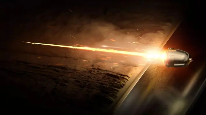
Halliburton Company has introduced the RockJet family of reservoir-optimised shaped charges for the optimisation of downhole performance.
The RockJet family of charges was developed at the Advanced Perforating Flow Laboratory at the Halliburton Jet Research Centre using real rock under downhole conditions, and are the first charges to be certified using the American Petroleum Institute’s new perforation witnessed test protocol.
The charges allow for operators to enhance well productivity by providing optimum reservoir connectivity through deeper formation penetration and a larger perforation tunnel diameter downhole. They help increase production and improve well productivity by improving reservoir contact through deep and clean tunnels which extend beyond the damage zone.
When tested at downhole conditions, the RockJet charges delivered 22% higher penetration and an 83% increase in area open to flow.
Chris Tevis, Vice President of Wireline and Perforating services, Halliburton, said, “The RockJet family demonstrates our commitment to develop innovative technologies that drive increased production for our customers. In the perforating business, optimising penetration depth and flow area is the key.
“A lot of companies may have charges that are tested on the surface, but how they perform in downhole conditions is difficult to prove. By following the API’s new test protocol, we can provide our customers with confidence that the RockJet charges, custom engineered at JRC’s Advanced Perforating Flow Lab, will perform downhole.”
Page 17 of 25
Copyright © 2026 Offshore Network