OFFSNET OFFSNET
  • Home
  • About
  • News
    • Asia Pacific
    • Australia
    • North America
    • Latin America
    • Middle East
    • Europe
    • West Africa
  • Reports
  • Careers
  • Team
  • Contact
  • Conferences
    • 2026 Conferences
OFFSNET OFFSNET
  • Home
  • About
  • News
    • Asia Pacific
    • Australia
    • North America
    • Latin America
    • Middle East
    • Europe
    • West Africa
  • Reports
  • Careers
  • Team
  • Contact
  • Conferences
    • 2026 Conferences

Sign up for our newsletter

Asia Pacific
Australia
North America
Latin America
Middle East
Europe
West Africa
{loadmoduleid 1581}

Latest News

Aging Well Stock Management in the Middle East

  • Region: Middle East
  • Topics: All Topics, Integrity
  • Date: Feb, 2017

Introduction

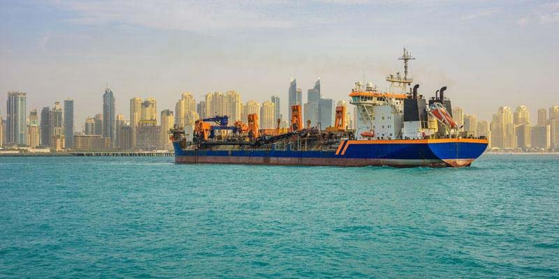
The Middle East offshore market generally has shallow water depth operations in high salinity water environments. As fields in the Arabia Peninsula mature and production declines they need extensive recovery enhancement and workovers which place added stress on the asset. In conjunction with the age and salinity of the water these works can effect the structural integrity of aging wells. This forces further works to take place, including diagnostic runs and tubing remediation.

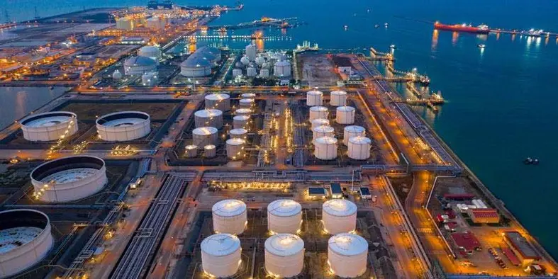
In the Middle East companies including Saudi Aramco, QP, Zadco and ADMA-OPCO have become experts in dealing with mature offshore wellstock, and below is a case study from the region highlighting the best practice that has been learnt.

Middle East Experience of Aging Well Stock Management

With a global slowing of drilling activities, we are often finding ourselves working over mature fields with old well stock to encourage greater recovery volumes and meet the demand for hydrocarbons. Mature assets have unpredictable behaviors, and this demands highly skilled teams and well thought out intervention activities to ensure the continued production of these assets. >Case One: The Well

In one example the Middle East operator observed live wells having fluid mobility into annulus space, resulting in the bleeding of hydrocarbons at the surface. The Annulus-B pressures were reaching 1000psi, and there was clear evidence of communication within casings. The hydro-testing of annulus space showed the wells were unable to withstand the test pressures, so ultrasonic testing, cement bond logging, and other logging techniques were used to quantify the integrity and accurately identify leak paths ahead of restoring the well integrity of failed Annulus-B wells. It was decided to repair the conductor pipe and perform casing patches externally and internally and cement consolidated rock formations, then cover with a tie back. As a remediation strategy, a cement barrier was placed in production casing above the reservoir using sleeves, patches, perforating two-zone techniques and milling to mention a few.

The utilization of section milling as a remediation measure is interesting. Its effectiveness was later verified with cement bond logging to ensure that integrity was assured. The operational challenge faced from leveraging milling technology was a failure to pass the bottom of section mill cut. This was then solved by using a taper mill to drill the required section.

The root cause of the integrity issues were understood to be generic aging (the wells were approximately thirty-years old), poor cement jobs and the possibility of ineffective drilling practices used at the initial stages of the well’s life. The core objective was to restore to well integrity of production and injection wells and rule out well abandonment as an option. This was achieved and the programme was a success – resulting in the extension of the mature asset’s life.

Case Two: The Conductor

In this case the operator discusses two fields in the Arabian Peninsula, one consisting of 99 wellhead towers, and the other having 116 wellheads towers – cumulatively the integrity department is having to manage 217 wellhead towers. The technical challenge faced by the operator is that over 60% of these wellheads towers are in life extension phase.

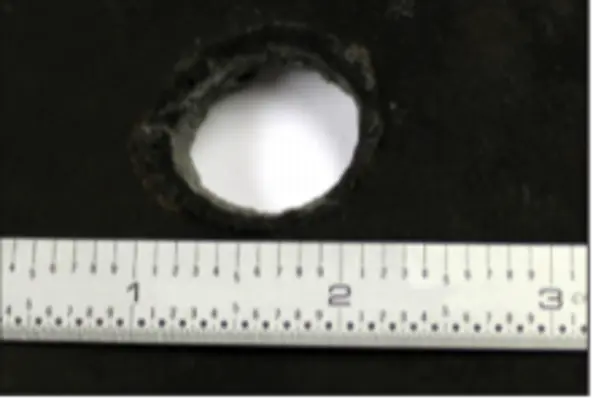
If offshore conductors corrode to the point their structural integrity fails, they are bound to buckle leading X-mas tree and other related critical equipment to fail.

The wellhead towers are typically 3-legged and 4-legged (with 9 slots) having above water guide support and near seabed conductor support. One of the main issues the operator is facing is having 9 slots conductor’s exposure to the huge amount of wave load which may transfer through conductor guides followed by jackets to piles. It is important to highlight conductor guides support for the wellhead towers is necessary, otherwise, the conductor will be free standing and may subject to vortex induced vibrations which could fail under free vibration or due to fatigue.

When designing conductor supports it is essential that the weight from X-mass tree, BOP, lateral support, vortex induced vibration, corrosion protection and marine growth should be considered among other requirements with respecting code and standards established by NORSOK, API, and ISO.

In the region operators have typical well conductor loading depth varying from 100ft to 300ft, having two types of loadings axial compression and global bending. The operational integrity is assured by conducting scheduled screen inspection (visual inspection) followed by detailed inspection using Saturated Low-Frequency Eddy Current (SLOFEC) and Pulsed Eddy Current (PEC) quantifying the minimum wall thickness, external and internal detections, separate mapping and other techniques.

By executing these inspections and then coupling them quickly with remedial works, abnormalities in the aging conductor were identified and rectified within the scheduled inspection window. In one example it was discovered there was at least a minimum wall thickness and therefore efficient strength to assure the stability of the asset against atmospheric, splash and full submerged segments of the conductor – and therefore its ability to cope with the stress of a work over for production enhancement applications was established.

The results of applying this conductor programme across the two fields showed that a robust remedial strategy, as emphasized by this operator, reduced rig intervention for replacement and fewer rig repair strategies such as reinforced cement, bolted clamps and welded sleeves just to mention a few.

Conclusion

Well integrity is becoming increasingly important in maturing fields in the Middle East. The asset integrity lifecycle is ever evolving, and lessons learned must be added to our codes of practice and become ‘the norm’ for future projects. This will ensure that collectively we are able to continue the efficient production from our existing assets for the benefit of future generations.

The insights captured in this document are indicative of a culture where we need a continuous improvement across training our personnel to increase competency, safety and cost-effectiveness of operations and use innovative approaches in low price environment.

From these examples, a scheduled approach to preventative maintenance workovers are shown to be more cost-effective overtime rather than dealing with sever and critical integrity works which are bound to follow.

INSPECTION OF JET PUMP HOUSING

  • Region: Middle East
  • Topics: All Topics
  • Date: Sep, 2019

INSPECTION OF JET PUMP HOUSING

This video of the month showcases how the application of CorrosionVA, supported by Integrated Video Caliper technology, helped an operator in Tunisia overcome a well integrity issue and maintain the safe operation of one of their high-rate production wells.

Wells operate under extreme conditions, involving exposure to challenging temperatures and pressures for extended periods of time.

Resins For Well Integrity Challenges: Curing Process

  • Region: Middle East
  • Topics: All Topics, Integrity
  • Date: Apr, 2018

Resin chemistry, including epoxies, phenolics, and furans, has been widely utilized in a variety of applications in well construction, completion, and production. This broad class of thermosetting polymers is physically characterized as free-flowing polymer solutions that can be irreversibly set to hard, rigid solids.

These resin systems are designed to solve a variety of well integrity challenges and offers common resin properties such as superior adhesion, resistance to many corrosive chemicals, excellent mechanical properties, low viscosity in the liquid state and flexibility and toughness after curing.

Reading tip: Materials for Plug and Abandonment of Oil and Gas Wells

TUNABLE GEL TIME

Despite these promises of performance, practical application of resin requires easy mixing and pumping without hardening before placement. What separates the different resin systems are the curing process. The best ones are developed with highly tunable gel time (from minutes to hours) over a broad temperature range, which offers a powerful tool for wellbore applications.

Read more: Effective alternatives to cement in oil and gas wells 

CHAIN PROPAGATION

Mixing such a resin system is fast and straightforward, and it is all about adding a curing initiator to a resin solution. The curing initiators do not take part in the chemical reaction but only activates the process.

Two fundamental steps are vital to the understanding of this curing mechanism: Initiation and chain-growth. The reaction is initiated by the introduction of free radicals to the liquid system. Free radicals are created from initiators, typically by heat. The free radicals are then transferred to the monomer, forming active centers that can attack other monomers. This is called chain propagation.

At a certain point, there is an abrupt change in the viscosity of resin liquid, with irreversible transformation from a viscous liquid to an elastic gel, called gel point. At the gel point, a resin solution undergoes gelation as reflected in a loss in fluidity. This marks the beginning of the formation of an infinite molecular network. Ultimately, all the molecules are added to the chain, resulting in the solid cured resin material.

IN CONTROL OF HARDENING

Different from conventional cement slurries and epoxies where the reaction starts as soon as mixing part A and part B is in a fixed ratio, the major benefit with free radical curing systems is that they can be cured predictably. This is due to the formation of free radicals is trigged by heat, and the rate of reaction is controlled by temperature. Therefore, such resin system remains liquid while mixing at the surface as long as it is not exposed to heat, and won't react before it reaches its designed target temperature. It would avoid hardening before placement, causing damage downhole or to the surface equipment used for mixing and pumping.

Read more: Cement plugs: A routine or a nightmare?

Read more: Plugging in depleted reservoirs

Free Guide The most common causes for leaks in oil wells and 8 questions to consider before you select solution


TGT confirms ability to accurately quantify integrity status in wells completed with high chrome tubulars

  • Region: Middle East
  • Topics: All Topics, Integrity
  • Date: Jan, 2018

TGT has recently taken its electromagnetic EmPulse® well inspection system to new, more complex and challenging levels with recent successful surveys on wells with very high-chromium tubulars. EmPulse’s capabilities are likely to be particularly applicable for Middle East operators, and also some fields in the Gulf of Mexico, the North Sea and offshore Brazil.

As downhole well conditions become more corrosive, alternative steels and corrosion resistant materials are being considered in the completion process – particularly chrome, nickel and molybdenum. Increasing chromium content helps protect well completions from highly corrosive fluids, such as carbon dioxide, hydrogen sulphide and chloride.

The increase in chrome and the resulting decrease in ferrous content, however, cause electromagnetic [EM] signals to decay too quickly for ordinary EM inspection systems.

Designed and manufactured completely in-house by TGT scientists and engineers, the EmPulse system combines ultra-fast sensor technology with ‘time-domain’ measurement techniques to capture EM signals rapidly and accurately in a wide range of pipe materials, including those with high-chrome content. This enables operators to evaluate pipe thickness and metal loss in multiple casing strings simultaneously, ensuring long-term well performance even in the most challenging production environments.

In three Middle East deployments – one an operator witnessed ‘yard test’ and the others in two live wells – TGT engineers demonstrated that the EmPulse system can quantitatively determine the individual tubular thickness for up to four concentric barriers, even when there are high amounts of chrome in the tubulars.

The Middle East operator-witnessed ‘yard test’ consisted of a 28% chrome pipe with built-in mechanical defects where EmPulse’s high-speed EM sensor technology correctly identified the man-made problems in a controlled environment.

The second operation took place in two live Middle East wells in a very high hydrogen sulphide gas production scenario with 28% chrome tubulars. In this case, the EmPulse system again functioned as planned, and recorded the status of three concentric well barriers. Additionally, a multi-finger caliper recording confirmed the electromagnetic results for condition of the inner pipe.

This ability to take measurements when facing specialised materials in certain well tubulars marks a significant breakthrough for TGT and the industry as a whole. The tests demonstrate how the EmPulse system can deliver accurate corrosion information, address a crucial information gap, and help protect well integrity in challenging production environments.


Engineered Perforating Solution Saves Operator 13 Days

  • Region: Middle East
  • Topics: All Topics
  • Date: Jul, 2017

Engineered Perforating Solution Saves Operator 13 Days Valued At $7.8 Million

CASE STUDY: OIL COMPANY CHALLENGE

Perforate the inner 9 5/8 in. casing of a well whose bottomhole temperature ranged between 300°F – 400°F using the largest possible diameter gun system to deliver 0.7 in. entry holes and less than 0.1 in. damage to the inner surface of the 13 3/8 in. outer casing.

OWEN SOLUTION

Develop, test, validate, build and deliver a unique gun system with the required performance characteristics.

SUCCESSFUL RESULTS

Acustom PAC™ casing puncher system was designed that exceeded the client’s requirements. On the first well, a 7.0 in. diameter 21-ft gun loaded 18 shots/ft with HMX explosives was fired successfully saving 13 days of on-site work compared with section milling. A successful cement plug was squeezed through the perforations to fully comply with abandonment regulations. Entry hole size averaged 0.75 in. and actual damage to the 13 3/8 in. casing was 0.01 in. to 0.015 in.

TIME SAVED = $7.8 million

Owen Oil Tools’ Energetics Technology Group undertook a special project for a major North Sea Service Company. Owen’s new PAC™, was designed, tested and produced to enable the operator to penetrate the inner string of two concentric casings as part of an abandonment program previously enabled by a time-consuming section milling technique.

Once the physical limits (9 5/8 in. casing ID) were considered, the engineering team addressed charge and gun system variables to achieve the requested performance. Maximum gun size imposed by the casing ID was 7.0 in. To ensure hydraulic isolation, the operator requested an 18 spf shot density to maximize communication of cement to the annulus. Explosive load, stand-off and shaped charge liner design along with casing properties were considered to determine entry hole size and depth of penetration. Centralization using a traditional bow-spring or solid fin stand-off ensured equal 360-deg performance around the casing.

Single prototype charges were tested using gun carrier sections and concentric casing targets under worst-case conditions to assess ballistic results. Tests confirmed the through hole size and damage to the outer string were within specifications.

Figure 1: Single charge test results (9 5/8 in. plate above, and 13 3/8 in. plate below)

A full system test confirmed that results could be achieved in a fluid-filled environment. Gun swell was checked to ensure the fired gun would not become stuck in the 9 5/8 in. casing. The last step was making a full production run of gun systems to satisfy the operator’s needs.

Owen Oil Tools
P.O. Box 568, 12001 County Road 1000
Godley, Texas 76044
P. 800.333.6936 – www.corelab.com/owen

Slickline Camera for Safety Profile Inspection & Parted tubing

  • Region: Middle East
  • Topics: All Topics
  • Date: Feb, 2017

Slickline Camera for Safety Profile Inspection & Parted tubing

This Video of the Month is from a well in the Middle East. The operator utilized EV’s Optis™ HD Memory camera to inspect the flow tube and flapper valve condition of a surface-controlled safety valve. Earlier intervention work had resulted in the need to fish tools at the valve but now the functionality of the valve was in question. There was communication across the valve but there was no access through it.

First, the operator decided to run a Lead Impression Block, which returned to surface with a half-moon shape impression. After seeing the impression, the Operator was not satisfied the results were conclusive and wanted a visual answer to identify what the obstruction was down hole.

EV were called in as an urgent service to give a clear answer. EV’s Optis™ HD colour memory camera capable of capturing 30 frames per second for up to 4 hours was deployed on Slickline to investigate. Once the camera program had completed, tools were pulled out of hole, footage was quickly downloaded and all soon became apparent.

The video shows the tubing had parted just below the DHSV. The camera exits the upper section of parted tubing and continues to run in. 4m below, the lower section of the parting can be seen, answering the half-moon shape on the LIB. With the assistance of the collapsible bowspring centralizers, the 1 11/16” OD toolstring was able to re-enter the lower section of tubing and continued to run in a further few meters.

While Pulling out of hole the camera exits the lower section of parting and re-enters the upper section of tubing capturing the DHSV components found to be in good condition.

The quick reaction from call-out to wellsite for EV to run EV their Optis™ Memory Camera allowed a definitive answer to the problem downhole in a matter of hours, saving the operator vital time & cost from making further unnecessary runs in hole, instead allowing them to plan ahead for the problem at hand.

Flapper Valve Milling Inspection

  • Region: Middle East
  • Topics: All Topics
  • Date: Jan, 2017

Flapper Valve Milling Inspection

This Video of the Month is from a well in the Middle East. The operator utilized EV’s Optis™ HD Memory camera to inspect the flow tube and flapper valve condition of a surface-controlled safety valve. Earlier intervention work had resulted in the need to fish tools at the valve but now the functionality of the valve was in question. There was communication across the valve but not access through it.

EV’s HD memory camera was deployed on slickline and here we find the actuated flow tube shifting up and down properly while the camera is stationary. The operator prepped the well by pumping clear water and shutting the well in to allow a gas phase to build at this shallow depth from the surface. On the same camera run but one meter deeper is the flapper valve which should open as the flow tube is cycled. However, the flapper is jammed in a partly open position allowing fluid to pass by but not equipment.

The operator decided to mill through the flapper with a hydraulic workover unit and requested EV’s HD memory camera to check milling progress if there were issues. The flapper valve was successful milled through but a subsequent gauge run stacked out 32m below the valve. The camera was deployed to inspect the milled area of the safety valve and the cause of the deeper obstruction. The video shows a very clean milling job in the flapper area with no potential hazards to hang up tools. 32m deeper we find part of the milled flapper has fallen and is now stuck across the well bore. The operator elected to install a temporary safety valve and return the well to production and will attempt to recover the fish at a later date.

Asia Pacific’s Integrated Services Market

Asia Pacific’s Integrated Services Market

  • Region: Asia Pacific
  • Topics: All Topics
  • Date: 26th March 2020

23

Gain insight into the growing Integrated Well Services Market in the Asia Pacific in this bespoke report by Offshore Network


{pdf=images/2020/03/Asia-Pacific-s-Integrated-Services-Market-Report.pdf|100%|800}

Download Attachments: Download PDF


WELL RIGLESS, RISERLESS LWI CASE STUDY

  • Region: Asia Pacific
  • Topics: All Topics
  • Date: Mar, 2020

23

Access a detailed well intervention case study that utilised cutting-edge rigless, riserless technology. See the full report from Sapura Energy which covers the Browse Basin project that took place offshore Australia.


{pdf=images/2019/09/OWI-AUS-2019-Content-1-Final.pdf|100%|800}

Download Attachments: Download PDF


Deployed Well Barrier Monitoring System

  • Region: Asia Pacific
  • Topics: All Topics, Integrity
  • Date: Jun, 2019

23

By Mark Plummer MSc BEng

Stuart Wright Pte Ltd’s (SW) CEO, Colin Stuart, and Well Engineer, Mark Plummer recently completed a one-year project supporting the Department of Natural Resources Mines & Energy (DNRME) in Queensland, Brisbane to perform a Well Programme Assurance Design and Construction Review (WEPA DCR) for high risk and complex wells.

The objectives of the WEPA DCR were to understand, by observation, how operators are meeting the relevant statutory provisions in the legislation; including subsidiary mandatory safety requirements, the Queensland Code of Practice and recognised industry standards.  Consistent with the Queensland government policy, the Inspectorate is collaborating with the industry to promote the safety and technical standards for petroleum and gas operations.

Following consultation and dialogue with industry, seven (7) Operators were selected as suitable candidates for the well programme assurance review. The programme was conducted in three stages as outlined in Figure 1 below.

Figure 1 – WEPA Design & Construction Review Process

WEPA Stage 1 – Understand with the petroleum operator, their well design protocols and standards, and agree specific well selection;

WEPA Stage 2 – Engage in well design and planning process of the selected well programmes; and finally; and

WEPA Stage 3 – Oversee well construction against the plan in the well execution stage. In particular to carry out well barrier monitoring and validation using SW’s proprietary Right Time Barrier Condition (RTBC) well barrier monitoring system.

Well Design Phase Review Methodology

Through discussion between the Regulator and each individual Operator, eight (8) suitable candidate wells were identified for the Well Programme Assurance review. Subsequently, a copy of Operator standards and well specific documents (e.g. Well Basis of Design, Drilling Programme, Drilling Fluids Programme, Cementing Programme, Casing and Tubing Design, Well Barrier Programme) were provided by the Operator for review by Well Inspectors.

The design phase review methodology was as follows:

  1. Tenure holders informed DNRME of the commencement of well design and provided relevant corporation documents/standards to DNRME.
  2. Inspector(s) from DNRME reviewed operator documents/standards and identified that they comply with mandatory regulatory requirements or noted any gaps.
  3. Inspector(s) from DNRME reviewed the well specific programme including ‘well basis of design’, ‘drilling fluid programme’, ‘casing & tubing design report’, ‘well barrier programme’ and ‘cementing programme’ to confirm if these documents were compliant with mandatory regulatory requirements and good industry practice.
  4. DNRME raised any clarifications arising from the standards and well design review with the Operator via a clarification register.
  5. DNRME provided a summary report containing any apparent non-conformance items for discussion with the Operator.

Well Construction Phase Review Methodology

Stuart Wright’s proprietary well barrier monitoring and validation system, RTBC, was used by DNRME to monitor drilling operations for selected wells. This exercise was the final stage for a given selected well, in DNRME’s WEPA DCR programme.

The system was used to assess each well for compliance, with their own standards and mandatory regulatory requirements. Specific barrier acceptance criteria were created in RTBC, which were extracted from Operator standards, the drilling programme and relevant legislation. Each barrier element during well construction was then assessed for reported validation, and assigned a traffic light colour (red, amber, green) rating depending on the result of the rating.

RTBC creates a Daily Integrity Report (DIR) capturing the barrier validation result.

The process of assessing compliance during well construction was as follows:

  1. DNRME set up a specific Barrier policy library for each Operator in RTBC
  1. DNRME set up a Well Barrier Plan based on the drilling programme, capturing all well construction activities and planned barrier validations
  2. DNRME received DDRs and other daily reports from the Operator from well spud until suspension/abandonment
  3. DNRME reviewed the operations stated in the Daily Drilling Reports (DDRs) and other daily reports and updated the barrier conditions and as-built diagrams in RTBC
  4. A Daily Integrity Report (DIR) was created for each day of operations for internal DNRME review before distributing to the Operator (see Figures 2A and 2B below). Any apparent gaps or discrepancies were discussed directly with the appointed Operator personnel

Figure 2A – Example Daily Integrity Report (Pg.1) – sent to Operator on a Daily Basis


Deployed Well Barrier Monitoring System Figure 2A 787x1024

Figure 2B – Example Daily Integrity Report (Pg.2) – sent to Operator on a Daily Basis

Key Findings

A range of useful findings arose from the WEPA study and, in particular, the use of RTBC to track barrier validation during well construction provided close monitoring and feedback which was beneficial to both the Regulator and Operator:

KF #1 – In general, the Operator standards compliance with mandatory regulatory requirements was good, but with individual exceptions which were fed back to Operators and improvement processes agreed.

KF #2 – Maintaining an overbalance margin to the bottom hole pressure (BHP) is a critical barrier during well construction. Operator standards for petroleum wells reviewed by DNRME could be further enhanced by stipulating a minimum overbalance to BHP requirement. 

KF #3 – Several Operators did not achieve regulatory compliance with the minimum 70% standoff for casing centralisation in their well design. The primary reason cited for this non-compliance was that the centralisation modeling simulation called for large sections of the casing having 2 centralisers per joint to achieve the required 70% standoff and Operators opined that the risks associated with running this many centralisers outweighs the benefit.

KF #4 – During the WEPA study, DNRME noted that the Operator’s design and planning process was often completed very late and, in many cases, only a few days prior to well spud which has an impact on risk during the well construction phase.

KF #5 – 75% of the gas-producing petroleum wells reviewed during the WEPA study were designed with standard Buttress Thread Connections (BTC) or Long Thread Connections (LTC) in the production casing string, which is common practice, deemed to be adequate as reservoir pressures were less than 3,000 psi.  For gas-producing petroleum wells, the selection of premium (gas-tight) connections would help to mitigate, over time, the risk of a leak path for hydrocarbon gas into the B-Annulus with associated consequences, though DNRME accepted that current industry standards support the common practice and the risk assessment approach currently used is valid.

KF #6 – The use of a barrier monitoring system demonstrated that Operators could not, in a limited number of cases, show compliance in all respects with their own standards and regulatory requirements during well construction given the conventions and format of the standard DDR reporting process. The Inspectorate had to review documents and data other than the DDR to complete the barrier validation picture.

KF #7 – The integrity reporting system used (RTBC) did give regulator and operator insight into escalating compliance risks. Furthermore, it allowed the Inspectorate to demonstrate in the captured database, a record that the operator is in compliance with regulation OR where they are not, it is transparent, and a flag raised.

KF #8 – The Daily Drilling Reports (DDR) focus is typically around performance and Occupational Health and Safety (OHS). However, no clear picture emerges in a typical DDR of an equal focus on well integrity and specifically loss of control risk.

Preliminary Conclusions of the WEPA Study

The findings and preliminary conclusions of the WEPA study were presented, on behalf of DNRME, by Colin Stuart at the Oil & Gas UK “Safety 30 – Piper Alpha Legacy: Securing a Safer Future” conference which was held in Aberdeen in June, 2018. A summary of the preliminary conclusions of the WEPA study is detailed below:

  1. There was some evidence of failure to follow approved plans during execution, particularly when problems developed. Management of Change (MOC) documents did not tell the complete picture.
  2. The use of a Daily Integrity system approach created transparency when deviations occurred, and forced better management response.
  3. The WEPA programme showed potential to reduce risk through better well integrity transparency. This could be achieved, as demonstrated, through the use of RTBC to properly identify Controls, assess that these have been Validated and record the Evidence of validation using a modern cloud-based data storage solution, which ensures data availability and instant retrieval and analysis.
  4. The WEPA process has important implications for Oil and Gas wells but also emerging Geothermal well projects where, due to the current absence of global standards, compliance challenges exist.
  5. The WEPA approach could be deployed across several international regulators to create a limited but global barrier validation best practice and potential failure databasefor well construction, including all critical component failures affecting well integrity.

This project summary has been approved by DNRME.

Assessing the Impact of Changing Completions Guidelines

  • Region: Asia Pacific
  • Topics: All Topics
  • Date: May, 2019

23

Understand how the Completions Standardization Technical Committee (COMSTEC), comprised of members from Petronas MPM and regional operators and service companies are tackling three main operational inefficiencies: Packers, safety and flow valves and operational procedure.

APAC Well Intervention Market Dynamics and Opportunities

  • Region: Asia Pacific
  • Topics: All Topics
  • Date: Jan, 2019

23

In this article, we review the situation and prospects for the offshore well intervention market, with comment on best practice, based on a presentation at OWI APAC 2018 (Kuala Lumpur) by Dan Cole, McKinsey & Company.


{pdf=images/2019/01/owi_apac_2019_report.pdf|100%|800}

Download Attachments: Download PDF


Europe

Middle East

North America

Asia Pacific

West Africa

Latin America

Australia

  • 113
  • 114
  • 115
  • 116
  • 117
  • 118
  • 119
  • 120
  • 121
  • 122

Page 118 of 124

Linkedin
Twiter
Contact Us

Quick Links

  • Reports
  • Conferences
  • Contact
  • Terms & Conditions

Latest Update

  • Block G offshore EG undergoes asset integrity for field life extension
  • Helix sells its Shallow Water Abandonment business in Gulf of America
  • Major milestones celebrated in Harriet Alpha decommissioning
Address: University House, 11-13 Lower Grosvenor Place,
Westminster, London, SW1W 0EX
Phone: UK: + 44 (0) 20 3411 9937
Email: info@offsnet.com