Global well integrity and production optimisation expert Coretrax has successfully deployed the ReLineMNS system across three wells and expanded a total of more than 27,000 ft of tubulars, a world record-breaking project in the Utica Basin, for a major gas operator with its ReLine Expandable Technology.
With one of the expandable liners reaching 9,000 ft in its expansion, all installations smashed the previously held record of 7,243 ft by at least 1,000 ft.
The total setting time from beginning expansion to exiting the top of the liner took only nine hours per well over a total of seven days on location. Covering the well integrity issue with one full-length liner, the overall setting time was significantly less than that of competing products on the market, setting at approximately 1,000ft per hour.
Coretrax’s technology was deployed into each of the wells with a 4.25” outer diameter liner. On expansion of the liner, the post-expansion of the inner diameter was 4.1” with an internal pressure capability of well over 10,000 psi, covering the wellbore issues identified.
Scott Benzie, Chief Technical Officer at Coretrax said, "Our advanced no shoe expandable technology allows operators to effectively isolate well integrity issues and immediately proceed with their next operations without the requirement to drill out a shoe, enabling our clients access to huge time and cost savings on their projects."
“The engineered materials used in the expandable technology ensure reliability is maintained through the operation, resulting in a consistent expansion reflecting our attention to detail.
“Our highly skilled team members from the operations and applications departments were key to the success of this world record, and delivering our valuable services for each well. This project pays testament to the strong and trusting relationship we have built with our client.”
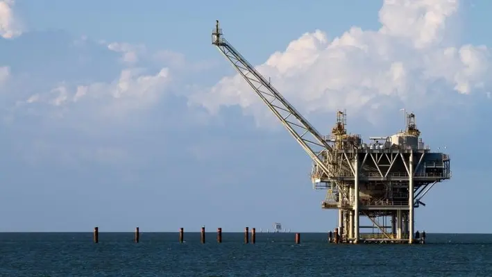
Energy services provider Danos has been awarded the opportunity to support the Promethean Decommissioning Company (PDC) and Petrofac alliance, to decommission multiple facilities in shallow water fields in the Gulf of Mexico.
CEO Paul Danos said, “Danos is honoured to join the efforts with PDC and Petrofac to provide safe and efficient operational and construction support for the alliance. We look forward to planning and executing this project with our partners and applying our 75 years of experience, safety and operational excellence in the Gulf of Mexico.”
The project, which began at the end of May, includes ten platforms, 196 wells and 32 pipeline segments in the South Pass and East Break fields of the Gulf.
This multi-year programme will allow Danos to support the PDC and Petrofac alliance and its decommissioning program with several of its service lines, including production workforce, construction, fabrication, and instrumentation and electrical.
Danos has many years of experience supporting decommissioning work through various service lines in the Gulf of Mexico as well as internationally.
“Having been appointed decommissioning operator for this project, we are delighted to have Danos join us and support the alliance we have formed with Petrofac. Together, our mission is to deliver safe, lean, integrated, best practices and technology-driven decommissioning operations which will reflect the highest ESG standards and include the minimising of GHG emissions/intensity and the environmental footprint of operations. Danos’ experience and knowledge will prove invaluable to the successful delivery of this program,” said Aditya Singh, President of Promethean Energy.
“Danos’ longstanding relationships in the Gulf of Mexico and comprehensive range of services positions them to provide the expertise needed for the programme,” a Petrofac representative said.
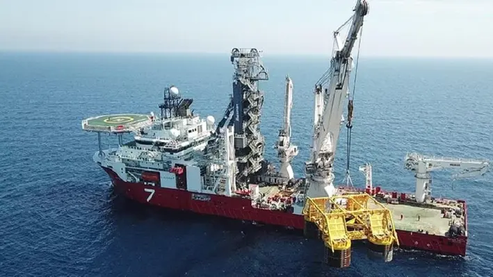
Schlumberger and Subsea 7 have signed an agreement to renew Subsea Integration Alliance for a further seven years.
Subsea Integration Alliance is a worldwide non-incorporated alliance between Subsea 7 and Schlumberger’s OneSubsea subsea technologies, production and processing systems business, to jointly design, develop and deliver integrated subsea development solutions.
Over the past seven years, the alliance has successfully combined the complementary capabilities and market-leading technologies of OneSubsea and Subsea 7, and worked collaboratively with clients to design, develop and deliver integrated SPS and SURF solutions proven to optimise the cost and efficiency of deepwater developments.
John Evans, CEO of Subsea 7 commented, “The success of Subsea Integration Alliance is a result of the drive and commitment of both Subsea 7 and OneSubsea to deliver an enhanced experience and outcome for our clients. Driven by the demonstrable benefits to clients of this mode of collaborating, integrated projects are expected to remain a significant component of the subsea market. We look forward to extending our relationship with OneSubsea as we address the opportunities of the offshore energy market.”
The alliance continues to build momentum and, in recent years, has been awarded major greenfield projects in Australia, Brazil, Africa and Turkey, as well as significant tie-back work in the Gulf of Mexico and Norway.
“Subsea Integration Alliance has proven to be a tremendous success,” said Abdellah Merad, EVP, Core Services and Equipment, Schlumberger. “Having been awarded 12 integrated projects and more than 130 early engineering studies around the world, it has helped– and will continue to help – customers achieve maximum value from their subsea developments through industry-leading innovation and expertise.”
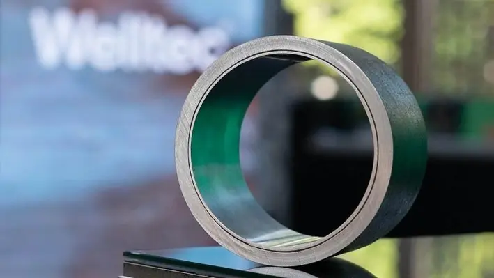
Welltec has formed an exclusive partnership with Isealate AS to become the largest shareholder in the innovative company which provides a patented patch-thru-patch technology.
Chief Commercial Officer at Welltec, Tommy Eikeland, commented, “Well leaks and damages are among the primary concerns raised by our customers during the intervention and workover phase. This acquisition perfectly complements our existing technology portfolio and adds a new dimension in terms of metal expandable capabilities. Once fully integrated, we will be able to set patches and Welltec Annular Barrier technology on either wireline or drill pipe, providing our customers with the ultimate re-lining and repair solutions for well integrity.”
Isealate’s downhole patches can currently be run on wireline and provide multiple benefits typically associated with straddles and larger steel patches without any compromise or trade-offs. The ultra-slim patches have a variety of applications from water-shut off and leak repair, to damaged casing or completion repair, whilst managing to maintain a near full bore ID with minimal restrictions allowing patch-thru-patch operations.
Isealate AS Founder and Board Member, Bengt Gunnarsson, commented, “The integration with Welltec will allow us to bring our unique technology to more operators and deliver it through a global partner with a proven track record. In the meantime, this enables our team to fully focus on further development of the unique patch technology
“Welltec has a truly international field service organisation and management support structure, along with unique engineering, mechanical and electronic capabilities, combined with inhouse manufacturing capacities, which made them the obvious partner choice,” Bengt added.

Helix Energy Solutions Group, Inc. has announced that it has entered into a definitive agreement to acquire 100% of the equity interests of the Alliance group of companies for US$120mn million cash at closing, plus the potential for post-closing earnout consideration.
Alliance is a Louisiana-based privately held company that provides services in support of the upstream and midstream industries in the Gulf of Mexico shelf, including offshore oil field decommissioning and reclamation, project management, engineered solutions, intervention, maintenance, repair, heavy lift and commercial diving services.
Helix said that the transaction aligns with its ‘Energy Transition’ business model, by expanding its decommissioning presence in the Gulf of Mexico shelf and advancing Helix’s ESG initiatives by responsibly supporting end-of-life requirements of oil and gas projects.
The transaction also augments Helix’s decommissioning and life-of-field maintenance service capabilities through the addition of Alliance’s comprehensive shallow water assets, including a fleet of Jones Act-compliant lift boats, offshore supply vessels, a heavy lift derrick barge and diving vessels, as well as plug and abandonment systems, coiled tubing systems and snubbing units.
The deal further positions Helix to further penetrate the North American decommissioning market, with published reports forecasting nearly US$3bn of decommissioning expenditures between 2022 and 2025, and the potential to expand into the global market. Based on the assets being acquired, the parties’ assumptions and market conditions, and anticipating Alliance's potential annual EBITDA in excess of US$30-40mn, the transaction is expected to add accretive free cash flow and diversify Helix’s asset base and revenue stream, at an attractive valuation.
According to Helix, the deal will help in preserving a strong financial position and liquidity, as Helix’s pro forma cash, liquidity and net debt would approximate US$145mn, US$186mn and US$119mn, respectively. The transaction is also expected to enhance the financial performance outlook, with expected continued improvements in free cash flow resulting in expected strong liquidity and leverage position.
Owen Kratz, Helix’s President and Chief Executive Officer said, “Based on a number of markets and regulatory drivers and our current expectations, we fully believe that the offshore oil and gas decommissioning market will grow significantly in the near term. This acquisition complements Helix’s present deepwater abandonment offerings by adding shelf and facility abandonment capabilities and significantly enhances our position as a full-field abandonment services provider, both in the Gulf of Mexico and globally. We also see possibilities to expand our opportunities within our existing late-life production business.”
Steve Williams, owner of Alliance said, “Our recent successes in acquiring and developing businesses and assets to establish Alliance as an offshore shallow water energy services company has led us to Helix, who we see as the industry standard in deepwater energy services.”
The acquisition is expected to close in mid-2022 and is subject to regulatory approvals and other customary conditions.
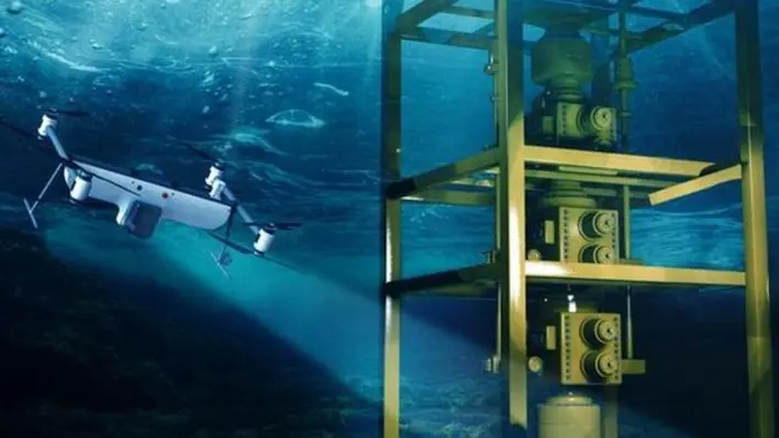
Defuzzy Labs, one of the leading robotics companies specialising in unmanned systems in the UAE, collaborated with SubUAS, the US company behind the Naviator Air/Sea Drone platform, to demonstrate its latest robotics fleet management solution and shed light on the future of offshore inspections.
The demonstration, which was held at the AWS Energy Symposium in Houston, featured the Sharjah-based operator instructing a Naviator drone fleet to perform an inspection from over 11,000 kilometres away, alongside the SubUAS team based in New Jersey, USA.
The live demonstration showcased Defuzzy's latest development of its robotics fleet management solution, which uses AWS's Roborunner service to command multiple Naviator drones over the cloud. This scalable and modular solution enables Defuzzy to easily integrate robots of various makes, models, and forms into the fleet and control them. The cloud services will further help enhance remote monitoring solutions and complete accurate robotic inspections, thus improving the safety and efficiency of inspection operations.
During the demonstration, Defuzzy engineers stationed in Sharjah, UAE, displayed their ability to monitor and command multiple Naviator drones located in New Jersey, USA. The fleet management solution automatically planned a mission and assigned it to the available drone in the background, after which the Sharjah-based operator was seen monitoring the fleet's status and the live video stream of the inspection routine.
Adnane ElSoussi, CEO and Co-Founder, Defuzzy, said, “We are pleased to announce that Defuzzy’s robotics fleet management solution will be used to command a fleet of offshore robotic platforms, which will not just be limited to drones, but a combination of USVs (Unmanned Surface Vessels) and other drones. Our robotic fleet management solution eliminates many challenges associated with inspections of offshore facilities, such as adverse weather and harsh operational conditions, limited and poor communication, availability of multi-talented inspectors, difficulty to access spaces requiring special tooling and equipment, high-risk operational environment, and lastly, high operational costs.”
Petrofac, a leading provider of services to the global energy industry, and Promethean Decommissioning Company (PDC), a pure-play decommissioning operator, will come together to decommission the South Pass 60, South Pass 6 and East Breaks 165 fields, offshore Gulf of Mexico.
The substantial scope of work includes work on nine platforms, 200 wells and 32 pipeline segments, all of which will need to be safely and assuredly decommissioned.
PDC takes on the role of decommissioning operator and is responsible for fulfilling the field decommissioning orders received from the U.S. Department of the Interior’s Bureau of Safety and Environmental Enforcement in February 2022.
Petrofac has been appointed by PDC as the decommissioning services provider in a contract valued at around US$200mn. The company will use its proven decommissioning programme management systems, tools, and processes to deliver the programme.
The PDC-Petrofac alliance has selected Danos, a leading Gulf of Mexico offshore services provider, for more than 75 years to support field operations and the decommissioning programme. With nearly 2,500 employees, Danos has a proven history of operational excellence and safe operations.
The project will be led from Houston, with the integrated alliance team using the latest digital software, including Petrofac’s proprietary project management tool Turus, to deliver the decommissioning project with comprehensive dashboards, transparency and assurance.
Nick Shorten, Chief Operating Officer for Petrofac’s Asset Solutions business, commented, “This significant contract recognises our industry-leading decommissioning programme management experience and our unique in-house capability to manage all well and asset decommissioning phases. It’s been more than four decades since Petrofac first began in Texas and in that time we have expanded our offshore capabilities across the globe. This expertise will be applied to the project, complemented by our already strong onshore presence in Texas.”
Aditya Singh, Founder and CEO, Promethean Energy Corporation added, “We are pleased to offer our new outsourced ‘decommissioning operator’ service to the industry and to commence activity on this major decommissioning project. We are fully aligned with all our stakeholders to improve environmental performance through the safe and efficient decommissioning of end-of-life assets. We accomplish this with a dedicated, fit-for-purpose entity, PDC, via an integrated operating service model and focused programme management. I am particularly pleased that the PDC and Petrofac alliance has been selected, leveraging the complementary strengths of both companies.”

Baker Hughes has launched the MS-2 Annulus Seal, designed to save substantial operational rig costs by reducing rig trips.
The new integrated sealing solution, the latest technological development to the MS-SN, has already been adopted by multiple customers in North and South America.
The MS-2 Annulus Seal integrates with Baker Hughes’ existing MS-800 wellhead system and helps to lower the cost of well construction and intervention, expands intervention options and ensures security and confidence of well integrity in challenging conditions.
“We constantly strive for technological optimisation and delivering the most advanced solutions to our subsea customers,” said Neil Saunders, Executive Vice President of Oilfield Equipment at Baker Hughes. “Through our new MS-2 Annulus Seal, we are helping to transform the subsea market and are developing quality technology that delivers long-term value, reliability and efficiencies for subsea customers.”
The MS-2 can be installed in a single trip, with an integrated lock ring that results in improved rig efficiency by providing immediate lockdown of up to 2mn pounds force without the need for a second trip, saving rig time. The MS-2 also provides easier access to wells, with no need for supplemental lockdown devices. It is tested to 20,000 psi, and to 200 load cycles ensuring life-of-field reliability and further demonstrating the seal integrity.
C-Innovation, LLC (C-I), an affiliate of Edison Chouest Offshore (ECO) and its family of companies, have signed a two-year contract for continued Riserless Light Well Intervention (RLWI) services onboard the Island Venture offshore support vessel.
The new contract follows a previous agreement in which the Island Venture performed interventions on multiple deepwater wells in the Gulf of Mexico.
David Sheetz, C-Innovation’s Vice President, said, “This new award is a continuation of nearly three years of setting new standards in the RLWI space. We are constantly working to change the way the industry looks at RLWI work to increase production in this ever-changing market. We look forward to the next few years on this project, and we are already making plans to expand the offering, including numerous dock upgrades to facilitate even more efficient fluid handling and waste removals to minimise required between-wells maintenance time.”
With no safe vertical access to several subsea wells under a platform, the C-I Subsea Projects Group was able to find a solution by utilising a well service jumper to perform well interventions. This collaborative effort between C-I and the operator allowed C-I to perform the intervention without disrupting the platform’s operations.
George Wilson, C-I’s RLWI project manager, commented, “C-I is committed to ensuring the continual improvement of the quality, health, safety and environmental aspects of its operations and services. The two-year RLWI work is no exception: with over one million man-hours, C-I had zero recordable incidents. So far this year, C-I has clocked over 135,000 hours with no recordables.”
Sheetz added, “The contract award for additional RLWI work is a credit to the entire RLWI team. Our team continues to provide creative solutions and methodologies to perform interventions that have not been achievable from a conventional RLWI approach. The collaboration of various subsea disciplines within our group has contributed to the successes, and our offshore teams continue to deliver on every execution that comes their way. C-I’s subcontractors, Halliburton, Baker Hughes and Caltex Oil Tools, were also key to the new award. I am extremely proud to work with some of the brightest people in our industry.”
C-Innovation, an affiliate of Edison Chouest Offshore (ECO) and its family companies, is celebrating its 15-year anniversary.
This milestone was reached by continuing to provide its customers with the most advanced remotely operated vehicles (ROV) systems and industry-leading ROV services. Such offerings have seen the company operate across the globe alongside major operators such as bp.
Since its foundation in 2007, the company has grown into the largest owner and operator of Schilling Robotics ROV systems in the world, with a fleet of 57 work class ROV systems. In addition to ROV services, it has now expanded into providing AUV, offshore survey, pipeline and well intervention services – recently demonstrated with the award of a light well intervention contract with a major operator in the Gulf of Mexico.
The addition of these services has steadily expanded C-Innovation’s footprint on the oil and gas industry.
Richard Bourque, Chief Operating Officer of C-Innovation, commented, “The past 15 years has seen multiple ROV companies come and go, while C-I has continued to grow and expand our offerings with additional vessels and advanced solutions.
“The key to remaining successful during a time when new competitors emerged and existing competitors faded away has always been the loyalty and hard work of our employees and the support of our clients. Reaching this 15-year milestone is proof to our clients and competitors that we are, and will continue to be, a leading ROV services provider in the oil and gas industry.”
Helix Energy Solutions Group, a leading provider of offshore energy services, has entered into a new multi-year contract with Shell Offshore to provide well intervention services in the Gulf of Mexico.
The three-year contract, commencing in March 2022, includes an anticipated 75 days utilisation per year with the option to add additional utilisation days.
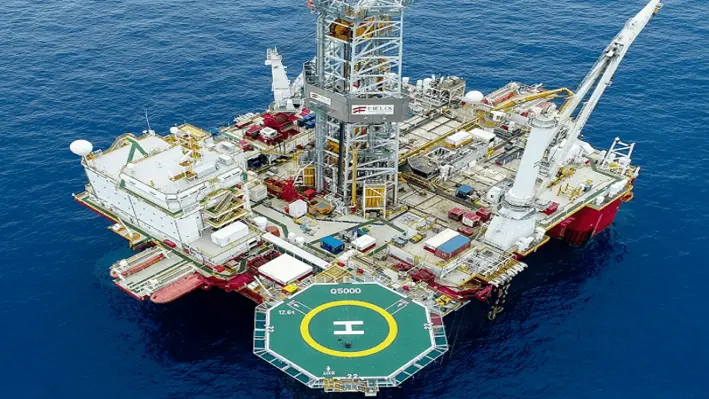
Helix will provide either the Q4000 or Q5000 riser-based semi-submersible well intervention vessel, a 10k or a 15k Intervention Riser System (IRS), remotely operated vehicles, project management and engineering services to cover operations from fully integrated well intervention to fully integrated plug and abandonment well services.
The Q4000 and Q5000 well intervention vessels provide an optimal platform for a wide variety of tasks, including subsea well intervention, field and well decommissioning, installation and recovery of subsea equipment, well testing and emergency well containment.
Scotty Sparks, Helix’s Executive Vice President and Chief Operating Officer, commented, “Shell continues to be a valued customer of Helix. We appreciate their continued confidence in our fully integrated well intervention services, our commitment to safety and cost-effective and efficient solutions. We are confident in the efficiencies and value we bring to our customers, and this contract further signals the increasing demand for our services.”

ROCSOLE has received an Offshore Technology Conference (OTC) 'Spotlight on New Technology award' for its Intelligent Level Detection & Data Analytics for Sand Management.
In oil and gas facilities, sand production is an unwanted element. Robust and reliable sensors are critical for automated sand management systems to secure the proper functionality and avoid unexpected shutdowns or reduced production rate.
ROCSOLE utilises leading-edge tomographic technology, its Separator Profiler is a real-time non-radioactive monitoring solution that physically sees and measures separator's emulsion layer, improving separation efficiency by optimising residence time and resulting in higher quality output downstream.
“We are honored by this recognition. Innovation is not just a one-day job; this shows that the community appreciates the continuity of our innovative work shaping the future of energy and process control,” said Mika Tienhaara, Chief Executive Officer of ROCSOLE.
This is ROCSOLE’s third OTC Houston Spotlight award with the company first being recognised in 2020 for its Liquid In-Tank Inspection (LITI) product. This was swiftly followed, in 2021, with the prestigious award being bestowed on the company yet again, this time for its Deposition In-Line Inspection (DILI) system. It is the first Finnish company that has ever won the award
“Being rewarded the Spotlight on New Technology award three times in a row is a huge recognition for our technology. Being able to detect waste streams, deposits and solids build-up in real-time is providing considerable benefits for our customers to improve their efficiencies and ESG measures,” said Arto Voutilainen, Chief Technology Officer of ROCSOLE.
Copyright © 2026 Offshore Network