Well-Safe has awarded a contract to Trendsetter Engineering for the utilisation of the Trident Intervention System and technical services for abandonments in the UK, North Sea.
The system will be deployed from the Well-Safe Guardian rig to conduct a multi-well P&A campaign for an estimated 320 day duration.
Trendsetter owns and operates five 15,000 psi subsea intervention systems for hydraulic, riserless light well and intervention riser-based operations. Their flagship intervention system, TRIDENT, utilises advanced technologies to provide high-spec capability in a lightweight and modular package, furthering Trendsetter’s goal of bringing innovation to subsea intervention.
Mike Cargol, Vice President of Rentals & Services for Trendsetter Engineering, commented, “We are excited to work with Well-Safe to bring TRIDENT to the North Sea for plug and abandonment operations. We look forward to providing our value-added intervention services and are eager to identify additional opportunities for collaboration for our two companies.”
Neil Ferguson, Operations Director at Well-Safe Solutions, added, “Trendsetter is an ambitious partner with a strong track record of technical delivery around the world. Adding this capability to the Well-Safe Guardian unlocks considerable operational improvements and time savings for our clients during well intervention operations.”
As part of the decommissioning facilities section of the upcoming Decommissioning & Abandonment Asia Pacific Workshop 2022 (D&A APAC), a contingent from Petronas Carigali will present on the potential for integration within the end of life space.
The formidable party from Petronas Carigali will feature Ahmad Zawawi Abdul Raja, Well P&A and Decommissioning; M Zhafran B Sulaiman, Head Decommissioning & Abandonment Facilities; and M Redzuan B a Rahman, Head of Technical Solutions.
")
The three members will help attendees to understand the opportunity for integrated resources for upcoming decommissioning projects and how well and facility teams can benefit from this.
They will also present case studies from Malaysia where collaboration for decommissioning has been a success, including the challenges and lessons learned from such projects.
")
Attendees will get the opportunity to hear all this from these industry experts, giving them a chance to ensure future projects are as efficient as possible.
With decommissioning emerging as a significant focus for the oil and gas community in Asia Pacific, D&A APAC is not one to be missed!
To learn more about the workshop: https://events.offsnet.com/DAAPAC2024#/
Or reach out to the details below for more information:
Erin Smith
Global Accounts & Australasia Regional Manager
T: +64 (0) 289 900 118
E:
At the OWI MED 2022, being held in Athens, Greece on 20 September, Matthew Vick, Senior Subsea Wells Engineer from bp will speak about their Gulf of Mexico riserless intervention campaign.
Attendees will have the exclusive opportunity to access a case study from bp on their ongoing riserless Intervention Campaign in the Gulf of Mexico.
Vick will review the broad scope of well access equipment that can be utilised from a single vessel, including mechanical wireline, hydraulic via TRT, hydraulic via well service jumper hose and hydraulic via stimulation choke insert.
During the talk, he will explore an overview of the planning and execution of the campaign including well access, well integrity restoration, well surveillance, well stimulation and protection, and fishing.
")
OWI MED allows attendees to access new regulations and innovative LWI technologies to develop a best practice intervention strategy for production, integrity and P&A projects.
Reach out to the details below:
Joseph Watson
Project Manager
T: +44 (0) 20 3409 5720
e:
At this year’s Offshore Well Intervention Latin America 2022 (OWI LATAM) conference, South America’s leading offshore forum, Rafael Purificação, wells integrity lead at Trident Energy, will guide attendees through well integrity challenges in mature developments.
The conference will allow participants to access new regulations and innovative intervention technologies in order to develop best practice offshore strategies for production, integrity and P&A projects.
")
Adding his chapter to this exciting upcoming exhibition of expertise, Purificação will begin by comparing current monitoring and testing methods to ensure barrier verification for well integrity throughout Latin America. He will then establish the acceptance criteria for new technologies within the region to ensure that those looking undertake campaigns are equipped with the most effective toolbox possible.
Finally, the wells integrity lead will analyse the probabilistic quantitative approach to well integrity in mature fields to create standardised workover programmes before opening the floor for questions from the audience.
Purificação’s expert presentation will be one of many at OWI LATAM as it returns for its third year on the 18-19 October 2022 in Rio. Representing the annual meeting point for members of the offshore oil and gas community in South America, this is an opportunity not to be missed!
View the brochure here:
https://www.offsnet.com/latam/conference-brochure
Or reach out to the details below for more information:
Rachael Brand
Project Manager
T: +44 (0) 20 3409 3041
e:
Ahead of the ‘decommissioning wave’ about to break on the Asia Pacific offshore community, the upcoming Decommissioning & Abandonment Asia Pacific Workshop 2022 (D&A APAC) will be exploring best practices around end of life management including an exclusive presentation from Kitti Kamkaew, Environmental Specialist for Chevron Thailand Exploration and Production Ltd.
Kamkaew will be surveying Thailand decommissioning practices and hazardous waste management lessons and will guide attendees through information on the Gulf of Thailand’s decommissioning progress before mapping out potential upcoming campaigns.
![]()
The Environmental Specialist will go into detail around Chevron Thailand’s offshore to onshore decommissioning waste management and will discuss lessons learned from dealing with hazardous waste in decommissioning processes.
Undoubtedly, some of the challenges Chevron Thailand have experienced will be felt by other operators looking to pursue their own campaigns in coming years. To learn about these and get the opportunity to pre-empt them ahead of time, be sure to attend D&A APAC.
To find out more, click here: https://events.offsnet.com/DAAPAC2024#/
Or reach out to the details below for more information:
Erin Smith
Global Accounts & Australasia Regional Manager
T: +64 (0) 289 900 118
E:
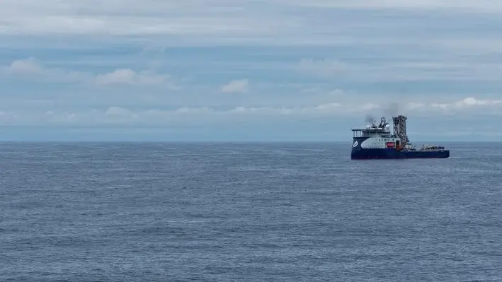
Nauticus Robotics, Inc., a developer of subsea and surface robotic services using autonomy software, has entered into an agreement with Shell to advance to the qualification phase for a more efficient means of acquiring subsea integrity data utilising Nauticus’ Aquanaut and Hydronaut robotic platforms.
The collaboration will enable Shell to add an advanced tool to its subsea asset integrity management lineup with the potential to improve subsea operations. Shell and Nauticus will collaborate with the industry’s leading inspection tooling service providers, to fully integrate into Nauticus’ robotic service solution.
An initial feasibility study for the phase-gated project was recently completed, and the team will now move onto the operational qualification phase, which focuses on remote operations of the robotic duo using supervised autonomy and tool control using Nauticus’ acoustic communication networking technology. The collaboration is targeting the preliminary work required for an offshore pilot project.
Todd Newell, SVP of Business Development at Nauticus, commented, “Working with a leading company such as Shell marks an exciting milestone for Nauticus, and this collaboration further validates the superior capabilities and extensive use cases of our robots across the energy sector. Implementing our supervised autonomous method – one that has proven more robust and dynamic than most of its kind – is expected to provide our partner and future customers more than 50% cost savings compared to today’s methods of operation.”
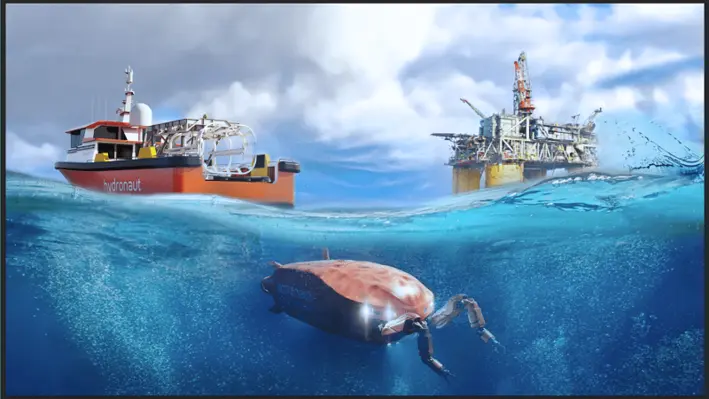
This collaboration will utilise the Nauticus’ flagship and fully electric subsea robot, Aquanaut, which is deployed from the company’s small surface vessel, Hydronaut –used for the transport, recharge, and communication for Aquanaut, among other tasks. Together, this robotic pair will function as a unified solution to bring a new means of conducting subsea work to the offshore services industry. Their inherent autonomous architectures will allow a transition to far more autonomous operations over conventional solutions.
“An exciting aspect of this project is the opportunity to combine the strengths of advanced inspection tooling with the advanced marine robotic capabilities developed by Nauticus Robotics,” said Ross Doak, Deepwater Robotics Engineer of Shell’s robotics team. “This project aims to fundamentally improve how we collect subsea facility data, through the combination of ‘AUV native’ tooling design, supervised autonomy, and recent improvements in remote communications.”

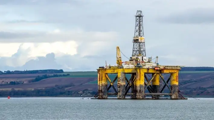
In an operations update, EnQuest has indicated that it is making good progress in its decommissioning project in the UK, North Sea.
EnQuest stated that the Heather and Thistle plug and abandonment (P&A) campaigns are progressing well with six wells completed at Heather and nine wells completed at Thistle. As a result, the group remains on track to complete the P&A of 16 wells at each installing in 2022.
In addition, the company noted that the tender processes for heavy lift vessels for Heather and Thistle topsides and jacket removals has concluded. Contracts to complete the scopes (scheduled for 2024 and 2025) are expected to be awarded in Q” 2022.
EnQuest also reported that, at the Dons, subsea infrastructure within the 500 metre zone is progressing as expected. Two phases were completed during the first half of the year and the final phase is scheduled for completion in August.
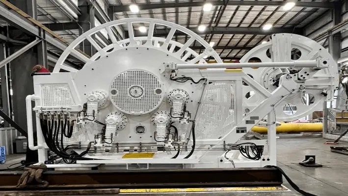
Logan Industries International Corporation, a machine designer, manufacturer, field service and repair company, has successfully delivered a unique, space saving coiled tubing (CT) reeler suite for OneSubsea.
Logan’s CT reelers are coiled tubing winches, where the reelers provide full torque control for the tubing without the need for a standard injector head. This reduces space required compared to standard tubing reeler / injection head combination, and allows for a larger fluid storage footprint on deck. When the equipment required to handle CT has a small footprint, more deck space can be dedicated to hauling fluid, which increases profitability for the operator.
This is the first unit Logan has delivered with a removable drum, which means the unit footprint can remain static on the vessel while the drums can be taken to a shore base for unspooling and respooling. They are transported in a purpose-built DNV lift rated drum basket, fully secured and protected. The swap out drum also makes the machine faster to build, reducing typical assembly time for the drum and drive train from two weeks to two days.
At 15,000 psi working pressure, 10,000 feet of 2 in. CT was provided on the drum, with live swivel and isolation valves on the unit. The suite of equipment provided for this work includes a spare drum, adapter to allow it to fit into most tubing service spoolers at the tubing manufacturer’s facilities, transport basket and lifting set along with the reeler, HPU, control stand and interconnect lines. Logan also provided a purpose-built overboarding platform with a translating / clamshell to accommodate OneSubsea’s unique end connection philosophy.
Dean Carey, Technical Director, Logan, commented, “We placed a work deck, dimple connector, test tool, controls and safeguards on this overboarding platform to give the crew plenty of access to the volume of space under the overboarding point. The overboarding platform also provided a reeler deck loading spreader effect on the vessel’s deck. We believe this is truly the next evolution in coiled tubing deployment offshore, and provides significantly more convenience for our customers. This is one of the most comprehensive reeler equipment suites Logan has had the pleasure to provide, and we expect it to remain in service for quite some time.”
Yerasimos Angelis, Managing Director of GA R&D Ltd., will be presenting a case study at the OWI MED 2022, which will take place in Athens, Greece on 20 September 2022.
He will speak about the highlights from over 300 U-line runs where this market-leading technology has reduced the cost and carbon impact of well intervention operations across the globe, including the North Sea.
The MD will explore U-line technology and how it can reduce cost and carbon impact of well-intervention. Along with demonstrating how the technology has improved the scope of well interventions that operators can achieve within budgets, he will also analyse how the services run on; slickline, e-line and fiber deployment.
The hottest talking points within the Mediterranean and North Africa region, along with the latest well intervention intelligence from the region will be discussed at the event.
")
Reach out to the details below:
Joseph Watson
Project Manager
T: +44 (0) 20 3409 5720
e:
The forthcoming Offshore Well Intervention Latin America 2022 (OWI LATAM) in Rio, Brazil from 18-19 October, will host a session on Transformative LWI Technologies by Rafael Rodriguez Fulco, Manager for Rigs Technology and Wells Reliability at Petrobras.
The detailed presentation will focus on riserless intervention and fostering a competitive solution exclusively for Brazilian portfolio. Rafael will evaluate a Brazilian P&A and workover scenario for riserless intervention to understand the strengths and weaknesses of this approach.
Attendees will be given a chance to understand Petrobras’ riserless homologation process timeline so that they can appropriately plan for integrated well integrity projects.
")
The session by Rafael will further review the competitive technical specification that embraces commercial and technical challenges to ensure best-in-class technology.
OWI LATAM will give the offshore community to convene and discuss scenarios specific to the Latin American market and come up with solutions in well integrity management tailor-made for the region.
To view the full programme click here:
https://www.offsnet.com/latam/conference-brochure
Or reach out to the details below:
Rachael Brand
Project Manager
T: +44 (0) 20 3409 3041
e:
As part of the early decommissioning works in Bass Strait, Esso Australia’s wells team is moving to the next stage of plug and abandonment work, applying key learnings from the recently completed conductor removal operations on Kingfish B and Mackerel.
Following its successful work at Kingfish B, Rig 22 will now be utilised for plug and abandonment activities at the non-producing platform, Flounder.
“The professional crew deployed with Rig 22 safely and efficiently completed operations at Kingfish B. The results proved the combination of our capable workforce and the refurbished Rig 22 can deliver world class performance for plug and abandonments,” said Wells Operations Superintendent, Ryan Turton.
“We now have a long programme ahead, and we are excited to further optimise our processes and continue to responsibly meet our plug and abandonment obligations.”
The team is also preparing for the arrival of the DOF Multi-Purpose Support Vessel (MPSV) Skandi Darwin, which is arriving at the Barry Beach Marine Terminal early August.
“One of the MPSV’s first tasks will be to support works at our steel gravity based monotowers, Dolphin and Perch,” said Matt Barney, Marine Field Superintendent.
The MPSV provides a floating support asset that will allow the complete abandonment operations on our non-producing facilities which do not have accommodation based on them.
“The MPSV hosts the workforce and means we don’t have to fly workers in and out of the area each day,” said Matt.
“We’re excited to start utilising the MPSV to expand our capabilities and adopt new technology to identify efficiencies, while ensuring the work can be completed safely.”
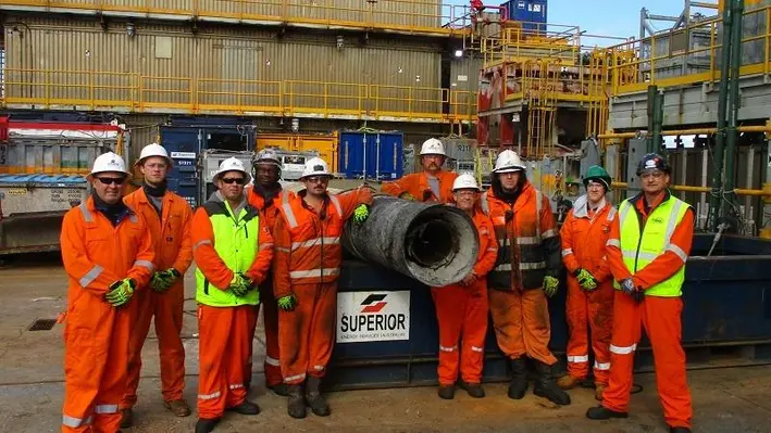
Thompsons of Prudhoe have successfully secured two decommissioning projects, working closely along with Heerema Marine Contractors and DeepOcean.
These two challenging contracts allow Thompsons of Prudhoe to provide a full turnkey dismantling and waste management contract solution to asset owner, Spirit Energy.
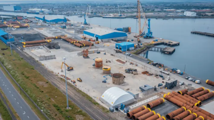
The six southern North Sea structures will be delivered into the Battleship Wharf Terminal by Heerema on two large North Sea barges during Q3 2023. The assets will be offloaded and transported using SPMTs to the purpose-built decommissioning facility in collaboration with our decommissioning partner the Port of Blyth and strategic subcontract partner Mammoet. In addition to this, DeepOcean will be recovering the subsea structures, rigid pipelines, flexibles, umbilicals and concrete mattresses and delivering them into the port using a variety of vessels from their versatile fleet.
After being involved in this important project since 2019, Thompsons of Prudhoe are proud to have now been chosen by two of the industry’s most recognised contractors to undertake these works. Mark Hill, Bid/Business Development Manager for Thompsons of Prudhoe, said, “We have worked hard over the last two-and-a-half years to establish a compelling and competitive decommissioning service offering. Having secured both, the topside and jacket dismantlement & disposal works for Heerema Marine Contractors, as well as the subsea waste management and disposal works for DeepOcean, is really beyond expectations."
Neil McCulloch, CEO of Spirit Energy and Industry Co-Chair of the Decommissioning and Repurposing Taskforce (DaRT), said, “Spirit Energy continues to create value with our industry-leading decommissioning capability and performance, and we are delighted that Thompsons have been selected, by our contractors, for the safe waste disposal of materials recovered from our assets. This builds on the excellent work that Thompsons have already carried out, at our South Morecambe Terminal, and demonstrates Spirit Energy’s ongoing commitment to support the local supply chain.”
Thompsons have begun working with all stakeholders including the Environmental Agency (EA) and the Health & Safety Executive (HSE) to successfully deliver these works over the forthcoming months. These recent project successes demonstrate and showcase Thompsons objective to become a trusted decommissioning partner to the oil & gas industry.
Page 85 of 122