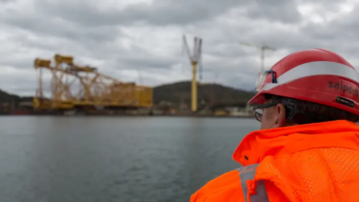
As part of the exciting lineup for Decommissioning & Abandonment Asia Pacific Workshop 2022 (D&A APAC), Idris Mohammed Jaafar, BSP Asset D&R Manager at Shell Brunei, will reveal how to improve efficiency and reduce costs in upcoming decommissioning campaigns.
As a huge proportion of Asia Pacific’s upstream assets move stubbornly towards cessation of production, operators are facing the unwelcome (but unavoidable) task of easing their structures into the end of life. Jaafar, in his expert presentation at D&A APAC, will help operators to undertake these operations with the least amount of cost expended.
")
Planning for aggregation to deliver the best value to D&R execution strategies and factors affection value and cost erosion in D&R will be among the topics the Shell Brunei will open the session with.
Jaafar will also explore asset integrity management in the end of life phase (noting what can be done to avoid high costs in D&R) and analyse technology deployment strategies that can be adapted to improve decommissioning and remediation activities.
A session not to be missed at one of the most anticipated offshore events of the year.
To find out more, click here: https://events.offsnet.com/DAAPAC2024#/
Or reach out to the details below:
Erin Smith
Global Accounts & Australasia Regional Manager
T: +64 (0) 289 900 118
E:

Baker Hughes has announced that it is acquiring AccessESP, a leading provider of advanced technology for artificial lift solutions, to further transform core oil and gas operations by reducing costs and downtime for operators.
AccessESP’s ‘GoRigless ESP System’ provides proprietary solutions that enable an electrical submersible pump (ESP) to be deployed and retrieved with conventional, light-duty intervention equipment without the need for a rig or requiring the well production tubing to be pulled.
These technologies significantly reduce the cost of, and downtime between, workovers used in the replacement of ESPs, which is of increasing importance in offshore and remote areas.
Maria Claudia Borras, Executive Vice President of Oilfield Services at Baker Hughes, commented, “Combining AccessESP’s alternative deployment technology with Baker Hughes’ world-class ESP capabilities creates a truly differentiated solution for our customers. This transaction reinforces Baker Hughes’ commitment to transforming our core business by focusing on leading, future-proof technologies that support growth opportunities and enhance our portfolio.”
AccessESP’s innovative deployment system provides more efficient solutions compared with traditional methods. By reducing heavy intervention, operators can increase oil recovery, efficiency and profitability while reducing costs and managing resources more efficiently. Lightweight intervention systems also reduce HSE risks, while light workover techniques enable ESP maintenance to be completed more quickly and at a lower cost than existing methods.
AccessESP has approximately 55 employees with facilities in North America and the Middle East. The transaction is expected to close in the second half of 2022 and will be integrated into Baker Hughes’ Oilfield Services segment.
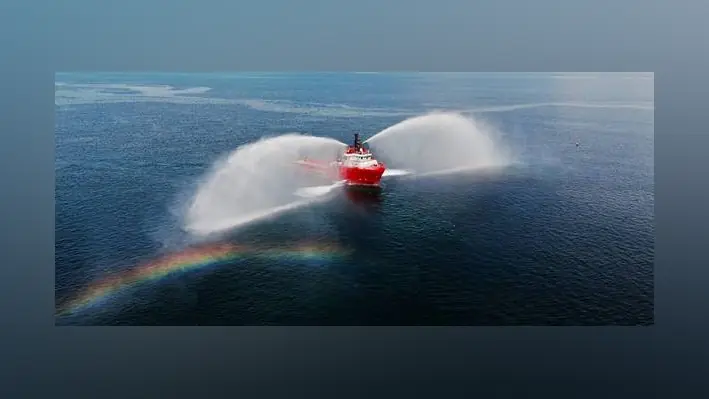
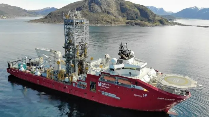
Paradigm’s e-Winch Technology, used by Archer aboard the Seafarer vessel in Norway, has received praises for playing an important part in significantly increasing well intervention efficiency while reducing CO2 emissions.
In 2020, Paradigm Technology Services B.V, a leader in oilfield technologies, delivered four NORSOK e-Winch units to Deepwell AS (now Archer AS) of Norway, for continuous operations aboard the Seafarer vessel.
Step changes in efficiency, performance and safety were core principles throughout the design and engineering phase, with the four double-drum units containing a wide range of Paradigm’s existing proprietary solutions as well as some new designs. Features such as dynamic breaking and constant speed control (taken from a suite of advanced winch control software options) have added significantly to the safety of vessel-based intervention operations, whilst the new ‘hands-off’ drum exchange system enable drums to be changed out safely without anyone ever being in the line of fire.
A wide range of operations have been performed with the e-Winch units, including plug and perforation, pre-P&A activities (plug setting, tubing punching/cutting), zonal isolations, production logging, injection logging, DHSV replacements, GLV changeouts and tubing/screen punching. Over the past year, the success of the whole Seafarer vessel has been notable and has been attracting industry attention having performed work on a large number of subsea wells within a short time frame.
The control options afforded by the e-Winch technology has helped significantly with the operational performance, with four winch control locations available to the team; a local hand-held remote control, a local deck mounted Zone 1 panel, a full control chair system with control panel with camera feedback situated in the vessel’s control room, and full remote operation from shore (or indeed anywhere worldwide).
William Ash, Managing Director of Paradigm Technology Services, said, “We are incredibly proud to be playing a small part in the success of the incredible Seafarer vessel. To fit such an amount of winch functionality into the restricted footprint was indeed a challenge, but with the great collaboration of all involved it has resulted in an excellent technical solution which is also helping drive down CO2 emissions with the all-electric e-Winch technology”.
Bendt Nybøe, Technical Lead Archer Husoy, added, “Due to the flexible set up, the easy rig up, the special safe drum change out systems, the advanced winch control software, the winches are performing even better and easier than we predicted.”
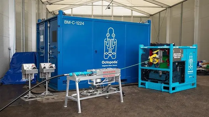
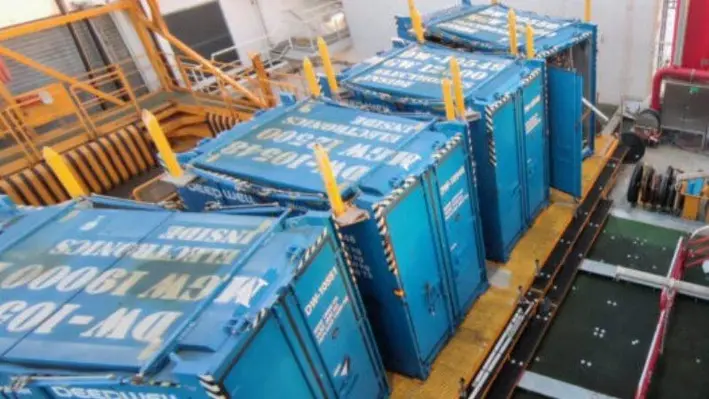
With integrity issues continuing to plague wells across the globe (affecting an estimated 30% of wells around the world), Expro has engineered the Octopoda annulus intervention system to enhance production and assure well integrity without disrupting operations.
According to Expro, the Octopoda is a unique, proven and advanced technological solution which allows direct access to the well annuli which can help bolster production rates, firm up well integrity and allows customers to regain shut in wells and make them economically profitable again.
With advanced corrosion protection for up to 20 years, Octopoda can help create a sustainable impact on asset production and revenue.
In a recent demonstration of its capabilities, Octopoda was used on a Chevron offshore platform well to intervene the A annulus and replace base oil with water ahead of resin placement on top of the packer.
Chevron had previously seen a 50% reduction in the impact of the resin when it was added to an earlier well containing base oil.
Deploying Octopoda meant Chevron avoiding the use of production tubing for circulation via a stimulation vessel or coil. This eliminated the need for communication between the production tubing and the A annulus meaning the barrier remained intact between the reservoir and the A annulus.
Expro displaced the base oil and established circulation by pumping fresh water through the annulus intervention system. Despite experiencing space limitations caused by control lines, clamps, and centralisers.
This was the first time the A annulus had ever been intervened using a conveying hose. Furthermore, it proved the efficiency benefits of Octopoda’s annular intervention over conventional practices by reducing time, costs and personnel. The operation lasted three days compared to an estimated 10-13 days, avoiding the conventional lube and bleed method or the need to punch and circulate the well.
Octopoda’s small footprint compared to a pumping vessel or unit reduced lifting risks and required only a two-man crew from Expro. The base oil was collected in a closed loop in the system, avoiding its exposure to the environment.
OWI MED 2022 is back as a live event after last year’s inaugural virtual launch. The conference will be held in Athens, Greece, on 20 September 2022. The hottest talking points within the Mediterranean and North Africa region, along with the latest well intervention intelligence from the region will be discussed at the event.
One of the key discussions at the conference will be learning how implementing new digital systems can result in more cost-effective and efficient well intervention and integrity processes. Operators can explore preventative maintenance efforts which can mitigate potential problems such as corrosion.
Contributing to this topic, will be Mustafa Adel Amer, well integrity specialist from BAPETCO. He will throw light on well integrity management, right from a production obstacle to a production booster. Mustafa will review surface-controlled subsurface safety valve (SCSSV) failure statistics in BAPETCO over the period 2010 to 2018. Mustafa will also explain the assessment of risk of failing in SCSSV and analyse wells criteria to define safe well operation with failed SCSSV.
")
Mustafa will be holding a panel discussion on ‘value of well integrity in reducing methane emissions’. It will seek answers to what the global industry can do or is currently doing to bring down its methane emissions from oil and gas operations. The discourse will explore the role of well integrity to reduce methane emissions for existing wells still in production and analyse whether well integrity has an impact in reducing methane emissions in abandoned wells.
Reach out to the details below:
Joseph Watson
Project Manager
T: +44 (0) 20 3409 5720
e:
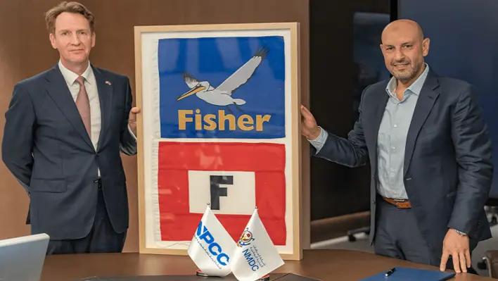
James Fisher and Sons plc and Abu Dhabi’s NMDC Group have signed a memorandum of understanding to collaborate on key projects and opportunities in the oil and gas sector as well as decommissioning, offshore wind and marine civil construction industries worldwide.
The two entities will develop a series of collaborative joint ventures and consortia to deliver major projects across multiple sectors, markets, and geographies. This will enable them to expand their capabilities jointly in areas such as offshore wind, turnkey oil and gas decommissioning, and accelerating the energy transition, a top priority for most nations today. They will bring their combined client base significant cost and operational efficiencies as well as additional choice in the market.
The initial focus for the partnership will be on diving opportunities within the Middle East region through James Fisher’s subsidiary James Fisher Subtech and the NMDC Group’s wholly owned subsidiary, National Petroleum Construction Company (NPCC).
Eoghan O'Lionaird, Chief Executive Officer of James Fisher and Sons plc, commented, “By leveraging NMDC’s extensive engineering capabilities, offshore asset base and financial strength, coupled with James Fisher’s geographic breadth, established market position, and specialist knowhow in decommissioning, diving, offshore wind and the energy transition, our alliance will allow us to co-develop more efficient and cost-effective solutions and capabilities to create value for customers at a scale and breadth that we could not do alone.”
Yasser Zaghloul, Chief Executive Officer, NMDC Group, added, “NMDC is focused on strengthening global partnerships as part of our strategic vision and to build on our credentials as a global energy and marine dredging EPC major. Over the past months, we have built our geographic footprint considerably. The partnership with James Fisher will drive collaboration in the oil and gas sector, including decommissioning, as well as the offshore wind and nearshore civils markets.
"We will share, in particular, our collective strengths and expertise to support the energy transition agenda. In addition to drawing on our substantial engineering and fabrication expertise, we can bolster James Fisher’s service capability through our extensive asset portfolio that includes a fleet of 22 offshore vessels.”

South America’s leading offshore well intervention and integrity discussion forum, the Offshore Well Intervention Latin America 2022 (OWI LATAM) be held in Rio, Brazil from 18-19 October 2022 and is set to feature a presentation by Danilo Colombo, Reliability and Risk Assessment Advisor at Petrobras.
Danilo will be using the session to discuss taking risk-based decisions in well integrity and establish how Petrobras has used the ‘MyBarrier’ platform to improve its integrity management.
The presentation will also allow the attendees a visual into the company’s cases of ‘Quantitative Risk Assessment’ to identify potential failures before they occur. Danilo will then explore the future of well integrity using data management and digitalisation to mitigate human factors and steps to make the correct risk-based decisions every time.
") OWI LATAM is all set to feature some of the world’s leading well integrity and intervention experts from global companies who bring with them the knowledge and expertise to spread across the Latin American offshore market.
OWI LATAM is all set to feature some of the world’s leading well integrity and intervention experts from global companies who bring with them the knowledge and expertise to spread across the Latin American offshore market.
To view the full programme click here:
https://www.offsnet.com/latam/conference-brochure
Or reach out to the details below:
Rachael Brand
Project Manager
T: +44 (0) 20 3409 3041
e:
As part of the forthcoming Decommissioning & Abandonment Asia Pacific Workshop 2022 (D&A APAC), representatives from Pertamina Hulu Energi will give an exclusive presentation on the regulatory updates shaping D&A activity in Indonesia.
Pertamina’s Karyadi Junedi, Senior Engineer Surface Facilities and Sophia Kangan, Lead Specialist Innovation Process & Facility, Ex. Pertamina, will act as the guides for this expert exploration of the latest publication of regulations in Indonesia.
")
In this masterclass session, attendees will hear a review of the integrity of offshore structures for future decommissioning campaigns and abandonment programmes as well as having the chance to discuss the impact of regulations for the upcoming D&A programme. For those looking to embark on such campaigns, this session will prove critical in ensuring everything planned is compliant.
To learn more about this session and the wider D&A APAC conference, click here.
Or reach out to the details below:
Erin Smith
Global Accounts & Australasia Regional Manager
T: +64 (0) 289 900 118
E:
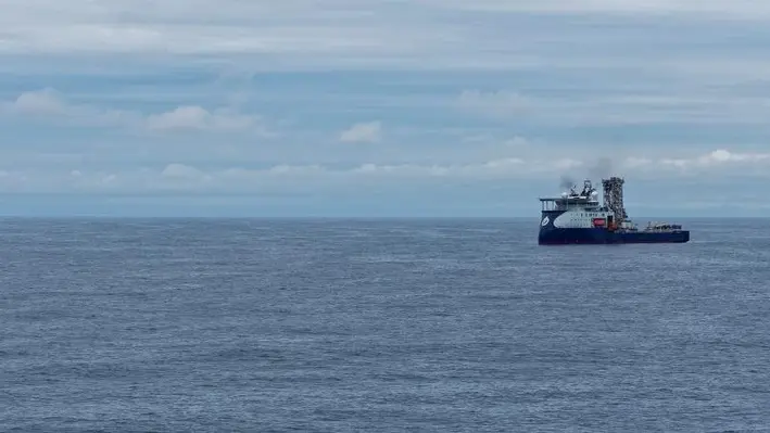
Seafarer, belonging to vessel-based subsea well construction and intervention services provider AKOFS, has just completed mobilisation for an upcoming three-well campaign as part of the five-year contract for well intervention for Equinor on Nowegian Continental Shelf (NCS).
The work has been performed at the Myklebust Yard in Norway. The OneTeam model implemented by AKOFS, was responsible for completing an intensive mobilisation without any serious safety incidents.
Following successful riser-less interventions since second half of 2020, Equinor and AKOFS have mobilised for a riser-based campaign using coiled tubing through an option in the contract. The AKOFS Seafarer has proven to be an extremely efficient vessel for riser-less interventions year round on NCS, thanks to its unique set-up, size and lay-out as well as the OneTeam model implemented by AKOFS and its operating partners Archer, WellTec and IKM Subsea. Utilising its flexibility, a high pressure work-over riser system has now been mobilised and added to the vessel together with a coiled tubing spread and fluid return treatment system.
The AKOFS Seafarer is now en-route to Equinor-operated fields Norne, Åsgard and Statfjord where well objectives will include scale, sand and debris removals, perforations as well as installation of plugs and screens.
Heerema has been awarded a decommissioning contract by Woodside Energy that includes the integrated engineering, preparation, removal, and transport of the Nganhurra riser turret mooring (RTM).
For the project, Heerema will remove the RTM from the Enfield field, located approximately 52 km northwest of Exmouth in Western Australia, by lifting the structure in one piece onto a barge and transporting it o Henderson or another suitable Australian port for dismantling, and recycling or reuse.
Jeroen van Oosten, Heerema’s Chief Commercial Officer, commented, “We are proud to be Woodside Energy’s contractor of choice for removing the Nganhurra RTM. This contract represents our first decommissioning project in Australia and although Heerema has a long history of safely and sustainably removing offshore structures from the North Sea and Gulf of Mexico, we are very excited to continue our responsible decommissioning operations in Australian waters.”
Heerema is looking forward to taking an active role in Australia’s decommissioning ambitions. The removal and subsequent reuse or recycling of offshore infrastructure is an essential final step in the lifecycle of oil and gas infrastructure and aligns with our company values of responsibility, sustainability, and contributing to a circular society.”
Serica Energy plc, a British independent upstream oil and gas company with operations centred on the UK North, has provided an operations update outlining its successful well intervention campaign on the Bruce Field.
Serica’s first ever light well intervention vessel (LWIV) campaign, part of the company’s ongoing plan to add value and extend the life of its Bruce facilities, has now concluded without any safety incidents or environmental issues.
The initial well (Bruce M1) was re-entered for the first time since 1998 and, after a successful scale removal and water shutoff, a significant reperforation and new perforation campaign was executed with the well returned to production.
Rates from the well have since increased from around 400 boe/d before intervention to more than 1,800 boe/d.
A similar programme was followed on the second well (Bruce M4) and production rates for the well increased from around 450 boe/d to more than 2,400 boe/d. The results from these two wells are at the upper end of the range of expectations and it is expected that there will be an uplift to independently assessed reserves.
This programme has increased confidence that further uplift can be achieved from future well interventions. Subsequently, plans to perform similar interventions on other Bruce and Keith wells, both subsea and from the platform, are now being accelerated.
Serica’s production performance in 2022 is benefitting from the significant investment in the Rhum R3 well reintervention, the Columbus development project and now the LWIV campaign. Serica’s average net production in July has averaged over 29,150 boe/d and YTD average net production is 26,832 boe/d.
Mitch Flegg, Chief Executive of Serica Energy, commented, "I am delighted with the significant progress that Serica has continued to make during 2022. The impact of the substantial investment programmes undertaken in the last three years has seen increased production levels providing responsibly sourced gas to the UK domestic market, protecting security of supply, and reducing the UK’s reliance on imports as part of the transition to a lower carbon future.
“Serica has no debt, limited decommissioning liabilities and with growing cash reserves is well positioned to continue to invest in further projects and other opportunities to add shareholder value. We have just completed a well intervention campaign on Bruce that has boosted net production by over 3,000 boe/d and provides further evidence of the value in Serica’s assets that can be realised through measured and expert operatorship.
“Operations have also commenced on the North Eigg exploration well with potential for transformational results, while we are now accelerating further well intervention work on Bruce and Keith following the success of the recently completed campaign.”
At D&A AUS 2022, Craig Costello from ASX Listed (T3K) TEK-Ocean Energy Services, provided an in-depth exploration of the company’s work within the abandonment space, explaining how it has inspected, refurbished, revalidated and recertified vintage well intervention equipment and assisted in decommissioning vintage oil and gas wells.
Speaking about wells and well intervention equipment, he presented cases of petroleum production companies with vintage subsea wells. He added that some of those wells were past their design lives and have integrity issues – both known and unknown problems. “The construction and production of these wells provided jobs for many decades. But it’s now time for these legacy wells to be plugged and abandoned, safely and efficiently,” he added.
In many cases, the required intervention equipment isn't readily available via OEMs – often because it has been retired. So this legacy vintage equipment, when it is available, requires revalidation, recertification, refurbishment and adaptation to the specifics of the project, Craig explained. Much of the legacy equipment is said to be redundant tooling.
There's an expectation from those who have worked on these wells for many years and from the broader community that the wells are abandoned safely and in a timely manner. “Increasingly, we're seeing NOPSEMA publishing directions and notices in regard to the decommissioning of wells, setting deadlines, and publishing information papers on decommissioning.”
Moving on, he presented three case studies to the audience, the first being the abandonment of some subsea wells by a semi-sub rig – Esso’s Blackback abandonment in the Gippsland basin; second was another subsea well set from a jackup rig: Esso’s Seahorse & Tarhwine abandonments; and lastly the Intervention Riser System assessment on Laminaria Corallina.
He informed that there were a lot of common themes for the three projects, one of them being that these are vintage subsea wells, with both known or otherwise unknown issues due to the lack of communication with the wells.
In all these cases, TEK-Ocean was able to provide alternative means to monitor the wells and barriers in both open water and drilling riser configurations.
Other common threads on these projects were:
• Intervening on wells past the original nominal design lives
• The vintage legacy equipment requiring revalidation, recertification and refurbishment
• Integrity issues on the wells
• Planning, innovative solution ideation and engineering.
Focusing on the first case study – the Blackback well abandonments – Craig said there were 20-year-old wells that had been shut for almost 10 years without any communications. “They have been lost from the Mackerel platform. So they didn't know the status of those wells. TEK-Ocean was selected as the lead subsea provider for that project for a turnkey solution to abandon the wells, requiring innovative approaches to get communications back to these vintage subsea control modules,” Craig added.
Hence, the scope of supply that TEK-Ocean provided for the solutions included sourcing equipment, conducting risk assessments and implementing a barrier philosophy for operational phases. The customer had supplied the vintage tree running tool and TEK Ocean recertified that.
“Re-establishing communications on these wells was a project in itself. Several pre-rig campaigns were executed to survey the assets, confirm the subsea interfaces functionality and to reduce the cost of the programme. This included ROV inspections, testing, opening and closing valves, cleaning, and debris removal."
Craig said establishing communications on those wells did take some effort as several of them that had not been attended to in a very long time and the equipment wasn’t readily available. “So TEK-Ocean was tasked with carefully assembling together a working system from three partial and broken systems that were available, with limited support and documentation from the OEM. This was successfully achieved.”
")
Craig informed that the Blackback wells were first attempted to be killed in 2010 via a bullhead operation from the Mackerel platform that was successful in two of the wells but it was later found that one had some internal leaks. “TEK-Ocean was not involved in the original bullhead operations but in the light of diagnostics, it was found that there was pressure on the wellhead above the master valves. Also, in 2015, communications were lost, so those investigations were a part of the 2019 campaign. The customer supplied a tree running tool, a 1980s vintage piece of equipment required for recertification and refurbishment. This recertification was achieved via crosschecking materials, part numbers, compatibility and suitability.”
One risk assessment flagged up that only one tree running tool had been provided. This was identified as a single point of failure and required de-risking because multiple runs of the tree running tool were going to be required. De-risking was achieved via a saver- sub approach that was designed, manufactured and project managed by Tek-Ocean for an integrated solution.
Moving to the second case study, he showed Seahorse & Tarhwine, which is in slightly shallower water in the Gippsland basin with 46 metres of water, and the abandonments were performed from a jack up rig. These vintage wells were drilled in the early 80s and then completed later that decade, but had been shut for five or six years, so they hadn’t been checked for quite some time. “The scope of supply in this case was a full subsea project management service again, using TEK-Ocean ISO accredited integrated management system, including all aspects of project management and engineering. The project execution plan was prepared including rig interfacing, barrier and emergency shutdown philosophies. Again, there was a TEK-Ocean managed pre-rig ROV campaign, including subsea cleaning, testing, to de-risk the rig campaign,” he added.
TEK-Ocean supplied and repaired all the equipment, again except for the tree running tool. In this project, the intervention riser system used was the TEK-Ocean dual bore riser system and this can operate down to 200 metres.
It was again a tight preparation and delivery schedule for this project. However, TEK-Ocean was able to mobilise in good time ahead of the required date set by the customer again with HSE performance and an operation during the peak COVID lockdown period in Victoria.
The third case study was the recent inspection and condition assessment of 1990s vintage Laminaria Corallina IRS. The inspection and condition assessment were carried out for both the upcoming suspension of the wells and for the future abandonment.
While concluding, Craig said that TEK-Ocean has a deep and broad knowledge of installed infrastructure throughout Australia particularly in the Carnarvon & Gippsland basins and that the company can support across all different project types. “These case studies demonstrate the recent projects that have been done in the last couple of years for major operators in the Gippsland Basin. We can help you achieve your cost and schedule goals on subsea well abandonments, and help you maintain a strong HSE performance record. TEK-Ocean is now recognised as a leading Australian company in the decommissioning space.”
")
Page 86 of 122