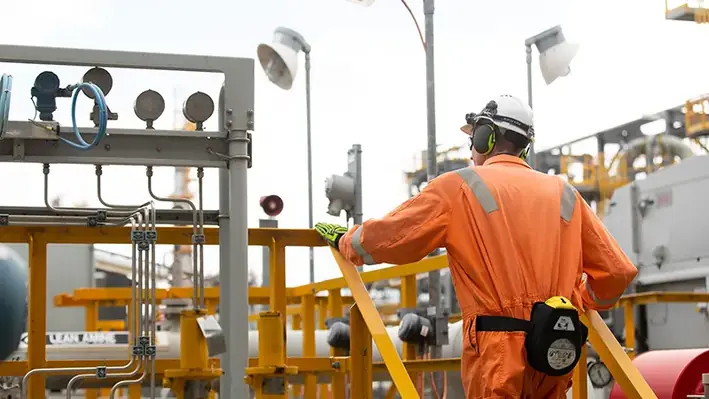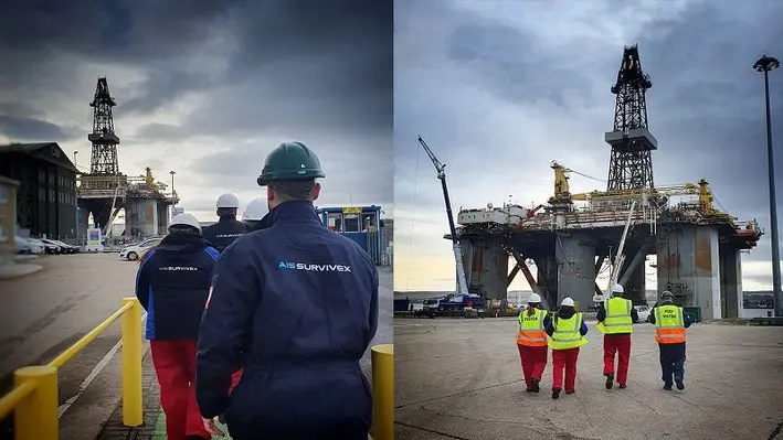
The team of AIS Survivex, an offshore training provider in the UK, has received an insight into life on board a decommissioning rig courtesy of Well-Safe Solutions.
Members of AIS Survivex were invited on board the Well-Safe Defender to let them experience life on a bespoke well plug and abandonment semi-submersible rig which accommodates 110 energy workers. It was described as an enlightening experience which allowed the team to understand more about the working conditions and challenges for the people they help train. AIS Survivex has been delivering and managing all training for Well-Safe since 2019 and is currently carrying out a range of training to prepare the Well-Safe Defender’s crew for its forthcoming campaigns.
The rig itself used to be used for drilling operations in the North Sea but, since being taken into Well-Safe’s ownership in 2022, has been converted to play a part in the energy transition as a bespoke well decommissioning asset. Currently, the rig is undergoing a host of efficiency enhancements ahead of its mobilisation this month for a well P&A campaign with Spirit Energy on the Trees and Chestnut fields.
laire Adams, Training and Competency Advisor at Well-Safe Solutions, commented, “With over 360 staff working for Well-Safe Solutions, we are focused on safe, smart and efficient delivery of well plug and abandonment – and all of this begins with effective training. AIS Survivex have supported Well-Safe Solutions on multiple occasions by providing multi-skilled trainers to provide rig-based training on all our assets as part of our rig readiness plans.
“Two AIS Survivex multi-skilled trainers were delivering a suite of courses to our crew onboard the rig to enhance personnel and team compliance against our matrix. The input of the AIS Survivex trainers is paramount in ensuring the relevant Well-Safe Solutions personnel held the correct training certification to ensure operational compliance prior to the rig mobilising for its upcoming P&A campaign with Spirit Energy. Collaborative working is key to our success and a safety-first mentality is critical for offshore workers.”
The spread consisted of a Horizontal Lay System (HLS) with the TTS-4/140 Series Tensioner, and a Generation 3 Reel Drive System. The scope covered recovery and installation of umbilicals and flexibles as part of an FPSO replacement. The project was part of the field’s infrastructure upgrade, aiming to reduce operational costs while increasing storage capacity and extending the production life.
The flexible products were handled through the vessel’s moonpool, enabled by the MDL HLS. The highly compact system allowed for efficient mid-line connections, by allowing safe and convenient hang-off for the product’s end terminations.
The integration of reel cradles and lashing points within the RDS track system facilitated quick mobilisation and demobilisation of the reels, as it eliminated the requirement for welding down cradles and reduced the requirement for pad eyes on the vessel desk.
As part of the scope, MDL also delivered the full sea-fastening design for the client’s back deck and provided materials and fabrication support to complete the mobilisation.
Euan Crichton, Project Manager at MDL, said, “This was an exciting project for MDL, partly due to the new location which grows further our West Africa track record, but also because of the short timescales the client was working to. For the Skandi Contractor, our compact systems proved to be the optimal solution. The HLS, tensioner and Generation 3 RDS make up a highly capable spread, enabling multi-reel installation over the moonpool.
“We are continuing our support to DOF in various global locations, configuring bespoke equipment spreads suitable to their vessels. So far, the open communications between the two companies have helped us zero in on the most efficient approaches to lay and retrieval scopes, to deliver maximum value.”
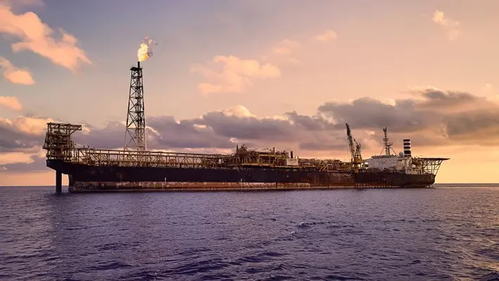
Jadestone Energy plc, an independent oil and gas production company headquartered in Singapore, has announced the Montara Venture FPSO offshore Australia restarted production operations last week.
Following what the company called a ‘carefully planned’ restart programme, production recommenced from the H6 well within the Montara field, with further wells set to follow, including the first Skua subsea well.
With the systematic opening of additional wells in line with the restart plan, production rates are set to increase, and the company will announce its production guidance for 2023 once output has stabilised.
Paul Blakeley, President and CEO at Jadestone Energy, said, “I would like to thank everyone in Jadestone who has contributed to the safe and successful restart of Montara operations as well look forward to putting this challenging period behind us and returning to business as usual.
“It is a relief to see operations at Montara being restored and we look forward to increasing production and cash flow. We also plan to return to growth, having completed three acquisitions within the last six months, with several new acquisition opportunities in the pipeline.”
The restart programme was instigated after the initial shutdown of production in July 2022 after a small leak from the crude oil tank aboard the FPSO was detected and required permanent repair.
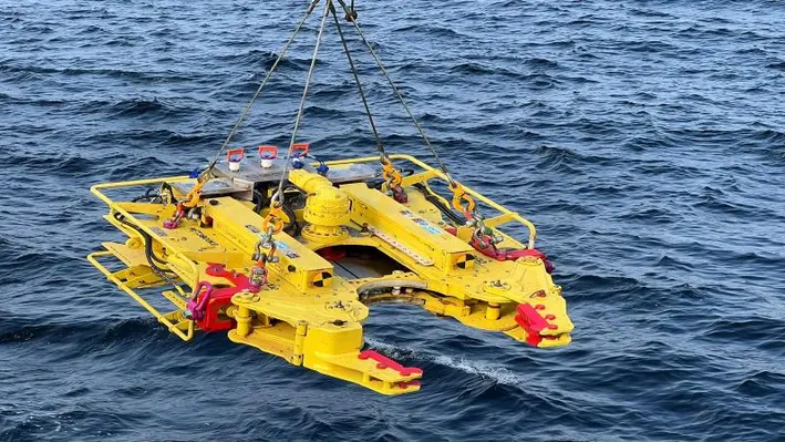
Decom Engineering’s specialist cutting technology has been successfully deployed on a decommissioning project in West Africa.
The C1-24 chop saw was deployed in water depths of up to 1,050 m as part of an operation to recover a jumper connector on behalf of Total Energies in the Gulf of Guinea, offshore the Democratic Republic of Congo.
The work scope included the cutting of the insulated 6” Duplex flowline at each end of the jumper, with the chop saw deployed by ROV with hot stab capability, and using a Tungsten Carbon Tip blade.")
The C-1 chop saw range is certified for use in water depths of up to 2,000 m, and has multiple buoyancy options, hot stab integration, blade reverse capability and bespoke customisation capabilities.
The Congo project follows other successful work scopes on behalf of major oil and gas operators and contractors covering the North Sea, Mauritania, Norway and the Gulf of Thailand.
Decom Engineering Managing Director, Sean Conway, said, “Our latest project in deep water offshore Democratic Republic of Congo is another tick in the box for the versatility, safety and efficiency of our cutting technologies, adding to an extensive trace record of completed work scopes in the major hydrocarbon producing regions.
“Decommissioning redundant piping infrastructure or repurposing asserts to be converted for low or zero carbon energy storage is a massive global market, and we are committed to investing in research and development to ensure our clients have the most sustainable means at their disposal to address their needs.”
")
Razor Energy Corp. in conjunction with FutEra Power Corp. has announced the successful construction, commission and operation of its co-produced geothermal power project in Swan Hills, Alberta.
The project combines an Organic Rankine Cycle (ORC) Turbine, which captures geothermal heat from the production fluid, and a Natural Gas Turbine (NGT). Both the ORC and NGT have grid interconnections which enable direct sales of electricity to the Alberta grid, and both systems have been running in a steady state while optimisation efforts are being made in order to reach the designed capacity.
Razor produces and injects large volumes of hot production fluid on a daily basis as part of its ongoing conventional oil and gas operations, and FutEra capitalises on that by capturing the geothermal heat energy from the fluid and using it to generate power with zero greenhouse gas emissions. The co-production element of the project means there is no new surface land footprint as the project utilises existing assets such as processing infrastructure, producing wells, produced water reinjection system and an operating gathering and distribution system.
In addition, the co-production approach enables Alberta’s fledgling geothermal industry to develop alongside the powerhouse of Alberta’s world-class oil and gas operations.
Justin Reimer, CEO of Emissions Reduction Alberta, said, “Alberta has long championed the geothermal industry. It is exciting to watch an idea for a pilot project grow into an industry-scale, commercial operation. This made-in-Alberta solution ushers in a new era of clean energy that will spur an entirely new industry in the province that taps into our existing oil and gas resources and expertise.”
FutEra’s next phase of the project will see the addition of solar, and potentially carbon capture, with the objective to create a net negative carbon emitting traditional oil and gas asset.
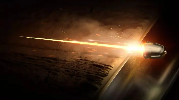
Halliburton Company has introduced the RockJet family of reservoir-optimised shaped charges for the optimisation of downhole performance.
The RockJet family of charges was developed at the Advanced Perforating Flow Laboratory at the Halliburton Jet Research Centre using real rock under downhole conditions, and are the first charges to be certified using the American Petroleum Institute’s new perforation witnessed test protocol.
The charges allow for operators to enhance well productivity by providing optimum reservoir connectivity through deeper formation penetration and a larger perforation tunnel diameter downhole. They help increase production and improve well productivity by improving reservoir contact through deep and clean tunnels which extend beyond the damage zone.
When tested at downhole conditions, the RockJet charges delivered 22% higher penetration and an 83% increase in area open to flow.
Chris Tevis, Vice President of Wireline and Perforating services, Halliburton, said, “The RockJet family demonstrates our commitment to develop innovative technologies that drive increased production for our customers. In the perforating business, optimising penetration depth and flow area is the key.
“A lot of companies may have charges that are tested on the surface, but how they perform in downhole conditions is difficult to prove. By following the API’s new test protocol, we can provide our customers with confidence that the RockJet charges, custom engineered at JRC’s Advanced Perforating Flow Lab, will perform downhole.”
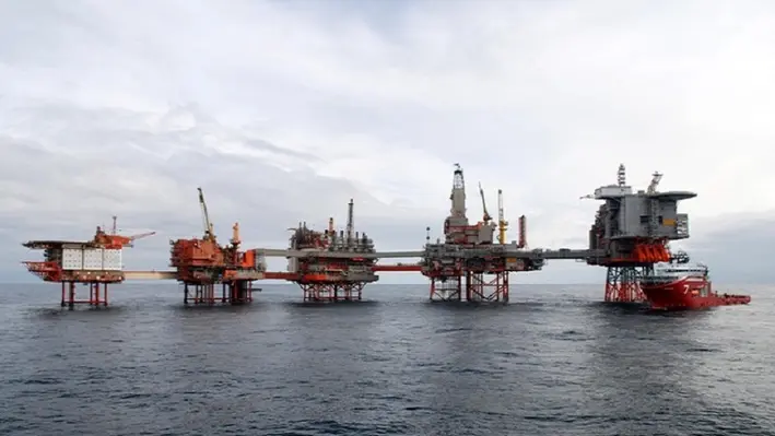
BiSN, a supplier of downhole sealing solutions and technology, has caught up with representatives from Aker BP regarding the successful plug and abandonment campaign conducted in the Valhall oilfield in 2020.
Aker BP needed to safely P&A 30 wells in the Valhall field in the North Sea and partnered with BiSN to deploy Wel-lok technology to create safe and cost-efficient Wel-lok plugs. After extensive testing conducted over the past two years, it has been shown that not only did this provide a permanent plug and abandonment solution, it allowed for new wells to be drilled and operated safely for the next 30 years.
“As part of the success story, we are monitoring the same wells today and we’re proud to say that out of the 30 wells today there is no leakage,” said Kjetil Vadset, Senior Drilling Engineer, Aker BP.
For two years prior to commencing the campaign in 2020, Aker BP and BiSN carried out a joint testing programme at BiSN’s Houston location to ensure Wel-lok technology was the safest, most cost-effective option. As a result of completing this rigorous testing programme, BiSN Wel-lok technology received acknowledgement of consent for use, including DNV-GL verification and PSA (NORSOK) evaluation of bismuth.
“Qualifying Wel-lok technology for use in the North Sea and securing a long term partnership with Aker BP were two major priorities for BiSN at the time,” said Paul Carragher, Founder and CEO of BiSN. “We are looking forward to continuing to develop a one team relationship with Aker BP on their forthcoming P&A campaigns.”
By implementing Wel-lok technology over traditional cement, it is estimated that the campaign saved approximately three months of rig time, or approximately US$2mn per well.
As part of the campaign, BiSN delivered the largest bismuth plug ever deployed to date. Produced at BiSN’s UK facility, the tool weighed in at 33,191 lbs and sealed up to 30 inches in the wellbore.
“We're very proud. The operation has gone beyond expectations. We planned and hoped for 72 hours per installation. We're down to 33 hours per installation just now,” said Vadset.
")
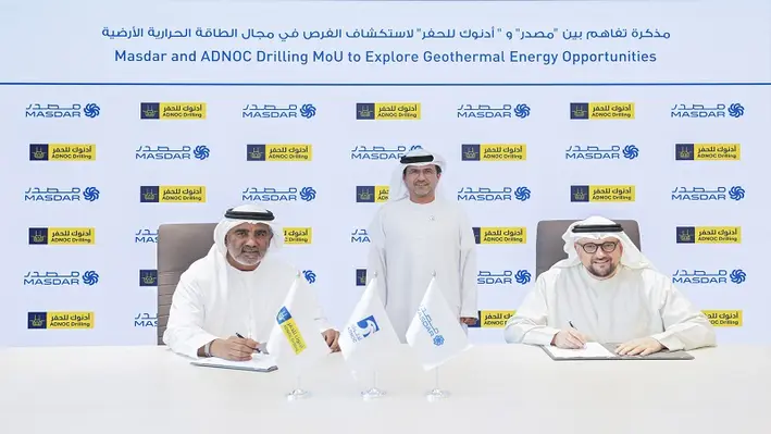
ADNOC Drilling Company has signed a five-year Memorandum of Understanding (MoU) with Masdar, one of the world’s leading clean energy companies, for the collaboration around development, investment, operations and projects to responsibly advance the energy transition.
Under the MoU, the company will engage as a drilling technical expert and advisor to support Masdar’s deployment of geothermal energy around the world. The companies will jointly evaluate the potential for ADNOC Drilling to provide geothermal drilling services.
Chief Executive Office for ADNOC Drilling, Abdulrahman Abdulla Al Seari, said, “Geothermal energy has enormous global potential and energy developers are challenged to ensure smart and innovative ways to deliver cost-effective wells. Our leading integrated drilling services offering can bring advanced, efficient start-to-finish drilling and completion technologies to enable Masdar the potential to generate clean geothermal energy to cool thousands of homes and office buildings.”
Mohamed Jameel Al Ramahi, Chief Executive Officer at Masdar, commented, “This MoU with ADNOC Drilling further reinforces Masdar’s commitment to unlocking clean energy opportunities across a wide range of technologies. With Masdar recently adding geothermal energy to our growing clean energy portfolio, we are excited about the important role that geothermal can play in helping to drive forward the global energy transition, and we look forward to working with ADNOC Drilling to realise that potential.”
Masdar entered the geothermal energy sector last month, with a strategic investment in Indonesia’s Pertamina Geothermal Energy (PGE), one of the world’s largest geothermal players.
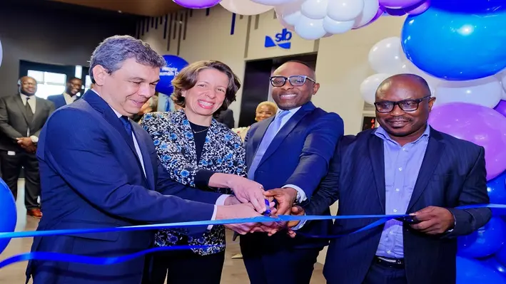
Global technology company, SLB, has officially opened its new West Africa regional office in Lagos, Nigeria.
In October 2022, the company launched a new brand identity to reflect its revised focused on energy innovation and decarbonisation and to forge the road ahead for the global energy transition. The new Lagos office reflects this new identity and will optimise employee experience and create a sustainable business environment for all stakeholders.
The modern design embodies the company’s sustainable roadmap through daylight harvesting, interactive and collaborative hotspots for employees, disability access and other features which bring forward the company’s evolved identity and culture.
Sopiribo Ideriah, Managing Director for SLB, West Africa, said, “As a technology leader, our unmatched market breadth, differentiated performance, and unique portfolio of products and services, has always positioned us for growth and advancement in the energy industry.
“All of this is owed to our people, who are the backbone of our organisation. I would like the thank all SLB staff – past and present – for their commitment and passion in delivering high quality services to our customers.”
The opening ceremony coincided with the 70th Anniversary of SLB’s presence in Nigeria.
“For seven decades, SLB has worked in Nigeria as a local company,” Ideriah added. “In 1952, SLB logged Nigeria’s first commercial oil well in Oloibiri, Bayelsa State, and has since logged several other historic wells in the country.
“Investing in local socio-economic projects and developing local talent through our borderless career culture, we have significantly contributed to the capacity development of Nigeria and are confident that we will continue to do business in ways that benefit our people, our society and the country.”
UTEC, a geo-services brand in Acteon’s data and robotics division, has launched ‘iSite Subsea’, a cloud-based platform which gives users an intuitive 360° visualisation of subsea assets and data.
It is developed from UTEC’s iSite collaborative virtual asset and data management platform and is specifically designed to meet the needs of the offshore renewable energy market and oil & gas subsea asset owners. Through iSite Subsea, users can source, view, manage and report on seabed, survey and asset data using a single secure cloud-based interface, enabling interrogation and comparison of data over time, remotely, 24/7 and without specialist software knowledge. Ultimately, this helps to reduce costs, lower risk, enhance health and safety, and deliver better informed decisions.
The new platform facilitates the digital delivery, throughout the lifecycle of a subsea asset, of geophysical, geotechnical, structural integrity monitoring, inspection, and maintenance surveys. It is designed to give developers and contractors access to the data they need to plan, evaluate, execute, and solve safety, environmental and risk scenarios. The end-to-end service delivery ensures that the latest data sets are always available to all users and eliminates the risk of double handling, incomplete data entries, multiple versions, and lost data/information.
“Energy customers have been using iSite to drive safety and efficiency, reducing costs on their above-water assets for more than 10 years,” said Paul Smith, Managing Director, UTEC. “We are now bringing the advantages of our product to the subsea market as a dedicated tool. iSite Subsea development has been driven by our customers’ needs. It is designed to help them reduce the time and costs associated with multiple visits, lower risk and achieve significant health and safety improvements through smart data management and interrogation tools that inform decisions.”
For the consideration of the secretary of state for energy security and net zero, Dana Petroleum (E&P) Limited has submitted a draft decommissioning programme for the Western Isles floating production storage and offloading (FPSO) vessel and its associated mooring systems, risers and dynamic umbilicals.
The associated infrastructure of the FPSO are located within UK block 210/24a in the northern North Sea which lies approximately 90 km to the northeast of Shetland and 58 km from the UK/Norward median line.
The draft decommissioning programme covers one vessel and associated subsea infrastructure including 12 mooring lines (three groups of four lines), nine flexible risers and two dynamic umbilicals.
![]()
Well-Safe Solutions, an international well decommissioning specialist, is supporting the decommissioning of two suspended wells in bp’s Kate field in the North Sea, 220 km from Aberdeen.
The programme of work, expected to be executed from the Noble Innovator jack up vessel during Q2 2023, will see Well-Safe Solutions carry out well engineering support services using its bespoke well decommissioning delivery process (WDDP).
Ruth Thomas, Subsurface Team Lead at Well-Safe Solutions, commented “We are very much looking forward to supporting bp with this work scope, which involves detailed subsurface and well engineering basis of design studies ideally suited to our specialist capabilities.
“Well-Safe Solutions will be instrumental in establishing and evaluating key subsurface isolation criteria including identifying and quantifying zones of flow potential and risks associated with redevelopment. In addition, we will also examine existing barriers and optimise the barrier strategy, taking into account the attributes of the region to safely and efficiently deliver this project.”
James Richards, Well Abandonment Director at Well-Safe Solutions, added, “The well decommissioning delivery process guides operators through the well plug and abandonment process efficiently and effectively, without the extended commitments and high costs historically associated with engineering resources over long periods.”