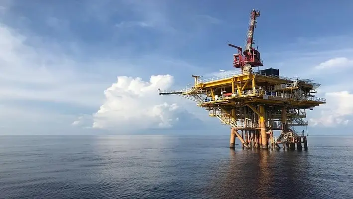
VAALCO Energy, Inc. (VAALCO) has completed two workovers at the Etame field offshore Gabon and added a total of approximately 1,050 gross barrels of crude oil per day.
As part of the campaign, VAALCO’s hydraulic workover unit (purchased in early 2021) was utilitied to rapidly mobilise and replace electrical submersible pump units. It was able to do this more efficiently than a drilling rig, which had cost saving benefits.
The longest producing ESP unit at Etame was replaced and upgraded in the workover of EEBOM-2H which increased production from about 500 gross BOPD (255 BOPD net) to approximately 1,400 gross BOPD (715 BOPD net).
Additionally both the upper and lower ESP units at the ET-12H well were replaced and the ESP design was configured at the same well. This restored production to 1,800 gross BOPD (920 BOPD net), an increase of approximately 150 gross BOPD (80 BODP net) compared to the average rate prior to the workover.
George Maxwell, VAALCO’s Chief Executive Officer, commented, “We are pleased with the results from these workovers, in particular, the 1,050 gross BOPD of additional production. We purchased the mobile hydraulic workover unit earlier this year to allow us to quickly and efficiently react to ESP failures and to proactively prevent ESP failures as we deemed necessary.
“This allows us to maximise production and even incrementally increase production, which is particularly attractive in the current price environment. We will continue to efficiently operate at Etame which generates strong cash flow to fund our accretive strategic initiatives.”
At the Offshore Well Intervention West Africa 2021 conference, Rafael Bastardo, Vice President of Global Sales, Silverwell, outlined his company’s Digital Intelligent Artificial Lift (DIAL) system, designed to eliminate production uncertainty, instabilities, deferment and operational costs.
As Bastardo explained, gas lift production optimisation is crucial to the future of the offshore oil and gas industry enabling operators to capture real value on their associated assets. ExxonMobil, for example, stated that they evaluated a 22% average oil gain using an optimised gas lift programme.
Traditional legacy Injection Pressure Operated (IPO) gas lift systems (in use for a long time within the industry) have narrow operating windows, injection depth limits, difficulties in assessing lift effectiveness, requires intervention to optimise, and is very sensitive to well dynamics. For this reason, Silverwell developed and released the DIAL system.
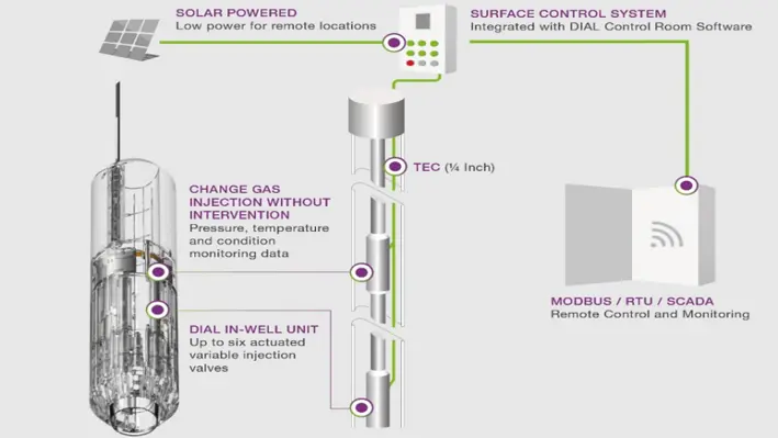
DIAL is a production optimisation system which integrates in-well monitoring and control of gas lift well performance with surface analytics and automation. Each DIAL unit has up to six independent injection orifices (with different port sizes) which can be individually opened and closed from the surface without requiring a drop in casing pressure. The suite of tools is connected to the surface via a tubing encapsulated conductor (TEC) that provides power and communications. This allows for continuous optimisation of gas lifted fields, remotely and without intervention.
To mitigate the challenges experienced by legacy IPO systems, DIAL boasts keys features such as patented binary actuator technology; variable orifice size at any depth; pressure, temperature and flow data; remote monitoring and control; intelligent field-wide management; and no deviation limitation.
These allow operators to capture key benefits such as:
-10% to 40% uplift
-Reduce +20% gas consumption
-Mitigate instabilities
-Deeper injection
-Reduce OPEX by 20% to 30%
-Reduce HSE risk
-No deviation limit
-Multi-million dollar NPV increase
-Eliminate intervention (does not require slickline to operate or adjust).
Unit Specification:
-A collapse pressure rating of up to 6,000 psi, with a 7,500 psi pressure rating coming soon
-10,000 psi burst rate pressure
-125 degrees Celsius max rated temperature, with a 150 under development and testing
-Concentric and slimline profile
-Multiple units per well
-Binary Actuation Technology
-Maximum choked flow rate of 6mmscfd/unit
-Electron Beam welded construction.
Bastardo noted that operators can acquire real time data from each unit, control each valve independently through a sophisticated surface control system and see key information such as the status for injection rate velocity, critical flow indicators and recent events that occurred during logging operation. Operators without SCADA can use radio or satellite communication to send the DIAL system data directly to cloud services which can be accessed remotely.
Silverwell are currently in the process of advancing the technology even further and will soon release units with a fully automated gas lift production optimisation system, drawdown control and water cut management and mitigation of injection pressure instabilities.
A reliable solution
The technology is relatively new (came into the market in 2016) however the trial phase is now complete and there are 15 wells installed with DIAL units globally. They are expected to be installed in 23 wells offshore by Q1 2022.
DIAL units are designed for a lifetime of over 10 years and, Bastardo added, the estimated savings from eliminating intervention was “immense.” He presented several business cases where, in each case, the technology had been very well received by the operator and had achieved substantial returns on investment.
Bastardo added that the best candidate for this technology were those with high frequency or high-cost interventions, assets with dynamic reservoir conditions, deviated wells and ones with constrained surface injection capacity.
In 2022, Silverwell is looking at releasing the system for subsea applications with pressure rating of 10,000 psi.

SRJ Technologies has announced that it has been awarded a new consulting contract and a contract extension totalling UK£100,000 by SBM Offshore.
The contract extension was won off the back of the successful completion of a previous contract to undertake detailed engineering analysis of SBM’s future FPSO designs. This was part of its Fast4ward programme.
Through the work, SBM will be able to optimise the design of machinery spaces without compromising integrity and long-term reliability. The contract extension covers additional in-depth engineering analysis to enable further FPSO design optimisation and to deliver additional cost savings.
The new consulting contract award is for a reliability analysis and maintenance optimisation to ensure safety system integrity on SBM’s FPSOs. The contract continues the consulting work SRJ has been delivering to SBM over the last year to support the ongoing implementation and roll out of a new ERP system across its fleet of FPSOs.
Alex Wood, CEO of SRJ, commented, “The SRJ consulting team is seeing great demand for its expertise in asset integrity management in all its forms – this cements our relationships with customers and gives us credibility as well as clear visibility of opportunities to sell our asset integrity solutions and products.”

The Centre of Decommissioning Australia (CODA) has appointed six industry leaders to form the organisation’s Supervisory Committee to bring increased strategic focus and expertise to the efforts to address decommissioning Australia’s aging oil and gas infrastructure.
CODA, which was established in March 2021, is uniquely positioned to drive collaboration in Australia’s oil and gas industry to collectively answer strategic questions about decommissioning options based on technical, safety and environmental knowledge. CODA's research shows there is more than $50bn of necessary offshore decommissioning work to be done — over half of which is anticipated to be started within the next ten years.
Francis Norman, CODA General Manager Decommissioning and Strategy, said the committee’s appointment marked a change of gear for CODA. He noted, “The support and input from a group of such experienced and engaged industry leaders will help accelerate CODA’s ability to work across the whole of Australian industry to build our domestic capability to address our own decommissioning needs, as well as position Australia to become a significant partner in the region’s decommissioning work.”
The committee consists of:
• Richard Perry — Decommissioning Manager, ExxonMobil Australia
• David Banks — Chief Technical & Marketing Officer, Santos Ltd
• Jay Southwell — APAC Subsea Services leader, Baker Hughes
• Brian Matthews — Marine, Subsea & Automation Manager, IAS Group
• Ineke Reyboz — Contracts and Commercial Consultant (independent member)
• Harvey Johnstone — Environment Director, International Association of Oil & Gas Producers (independent member)
“By applying research from the National Decommissioning Research Initiative, we and our industry partners will ensure Australia's future decommissioning activity will be built on independent and sound scientific research, providing the best possible outcomes for industry, environment and community,” said Norman.
Richard Perry, Decommissioning Manager, ExxonMobil Australia, said, “After an extensive history of successful resource development and energy supply across Australia, our national fields are starting to reach the end of their productive life leading to the dawn of a new industry, and with it, some fantastic opportunities.
“With the broad geographical expanse between major basins in Australia, CODA will be a crucial conduit to enable growth of this industry to be optimised for all parties throughout the supply chain and it is very exciting to be part of this journey.”
Jay Southwell, APAC Subsea Services leader, Baker Hughes, added, “The decommissioning era within Australia is swiftly gaining momentum, but it’s a complex subject. Strategic complexity requires an evolution in the way we share project and service information.
“With the launch of CODA, we now have a great opportunity to collaborate, share best global practices and make a real difference to support the Australian decommissioning sector to permit the safe removal of assets without impacting the environment.”
Contracts for CODA foundation phase projects have been recently awarded. Due for delivery in early 2022, these projects will build knowledge and understanding of the local decommissioning and recycling capability, provide Australian industry with an easily accessible digest of international best practice that can be used locally, and set out a pathway for innovation and new technologies for the industry. These include:
• Understanding the opportunity for local disposal and recycling pathways — Advisian
• Development of a decommissioning innovation and technology roadmap — Linch-pin
• Global review of decommissioning planning and execution learnings — Advisian
Odfjell Well Services and Odfjell Energy have announced the launch of a plug and abandonment (P&A) and slot recovery alliance alongside companies within the energy industry.
The agreement has an initial duration of two years with an option to be extended. It has been titled, the ‘Odfjell Collaboration Alliance’.
The aim of this alliance is to provide a complete service offering of rig, modular rig, jacking unit, wireline, plugs and all other services needed to successfully execute projects within P&A or slot recovery operations. The focus will be initially in the Norwegian market, with ambitions to expand beyond the Norwegian Continental Shelf.
Kurt Meinert Fjell, senior vice-president of innovation and development, Odfjell Energy, commented, “We are delighted to announce the launch of this strategic alliance, a move which will provide a high-quality oil service solution within the energy market.
“Each member was chosen for their strong history, forward-thinking approach and commitment to quality, and brings their unique area of expertise to support the P&A or slot recovery activities. We are confident that the multi-operator approach will lead to cost-effective solutions that will benefit our clients.”
The Odfjell Collaboration Alliance is managed by Odfjell Energy and Odfjell Well Services. The members include TCO Group, Ardyne, Wellstrøm, Altus Intervention, Control Cutter, JWS Gruppen, Tyrfing Innovation, InterWell and Innovar Solutions.
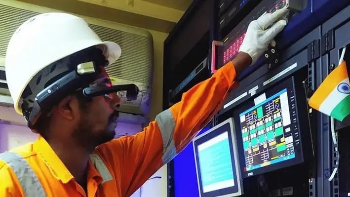
One of India’s leading marine service providers, OCS Services Pvt. Ltd (OCS), has awarded Fugro a two year contract to support its asset integrity and corrosion management operations off the west coast of India.
Fugro has establish a reputation for offshore operational excellence and has cultivated a successful track record in India, both of which were taken into account when the contract was awarded. Fugro will help OCS deliver on ONGC’s Protective Coating of Process Platform Project 1 (PCPP1), an infrastructure project to maintain and refurbish 32 offshore platforms in 7 clusters.
For the first time in India, Fugro will provide survey Geo-data and positioning via remote support solutions controlled from one of its state-of-the-art remote operations centres (ROC). Fugro’s integrated digital solutions will allow OCS to identify debris, seabed features, and subsea pipelines and structures near Process Platform areas to protect the marine environment from future damage.
Remote support will also enable OCS to monitor their operations in real-time and thus enable early decision-making as the project progresses.
Sangram Dhote, Director at OCS, commented, “This collaborative approach will set a new standard to managing the safety of operations in the Mumbai High Field.”
Swaminathan Subramanian, Marine Asset Integrity Manager for Fugro in India, added, “We are very excited to be awarded this contract and are looking forward to collaborating with OCS on a successful project delivery that benefits from Fugro’s remote operations expertise and the highest safety standards.”
The project is expected to be completed by May 2023.
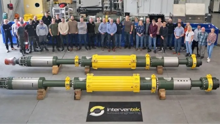
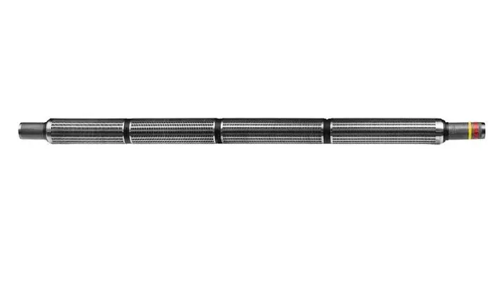
Interventek, a subsea engineering business, has launched a new API 17G qualified, in-riser subsea landing string system, named the ‘Revolution-7’.
The landing string is an advanced, 7-inch nominal, 10,000psi rated system incorporating Interventek’s unique Revolution safety valve – proven to provide superior shear-and-seal performance. The system also includes Interventek’s PowerPlus technology, which is a unique arrangement of a locally integrated, gas-accumulated power source.
The landing string incorporates lower and upper subsea test tree valves, a latch, a retainer valve and lubricator valve. A slick joint, shear sub and project specific adaptors enable space out in the BOP and interface with the tubing hanger running tool and landing string tubulars. The system components are integrated via pre-loaded connections which provide high operational performance and fatigue resistance.
The Revolution-7 landing string is market-ready and the first systems have already been dispatched to a customer.
The company believes the system is a stand-out solution, offering industry qualification to the highest standard, combined with advanced shear-seal valve technology, rapid failsafe gas-accumulated actuation, plus a range of technical, functional and cost benefits. The valve performs both cutting and sealing functions, using separate internal components, in a single rotation, reducing the need for the usual secondary valve to provide a post-cut seal.
With fewer, simpler components, the landing string system is compact and lightweight, but stronger and more fit-for-purpose. Supply lead time, redress and maintenance are faster, which in turn reduce project and lifetime costs. The system is suitable for deployment in all BOPs and its modular nature allows additional or alternative valve functions to be incorporated.
Gavin Cowie, managing director at Interventek, said, “Historically, operators requiring subsea landing string services have relied on a handful of tier one, integrated service companies that have their own fleet of proprietary systems. We work with both the operators and service companies to supply our advanced safety valves as system upgrades, where enhanced performance and functionality is demanded.
“In developing our offering, we are now delighted to be able to supply a complete subsea landing string system to a variety of customers in this market. We see a large and collaborative opportunity in providing cost-competitive and technically advanced solutions, to improve safety and operational efficiency for the wider industry.”
For subsea well completion, intervention, workover or decommissioning operations, a landing string is deployed from a floating vessel, via a marine riser, to enable safe and environmentally secure operations. The landing string system includes a subsea test tree which provides the capability to close in the well, cut any medium in the bore and disconnect in the event of an emergency.
The shear-and-seal Revolution valve technology used in the in-riser system is also compatible with open water, tree-on-tree abandonment and surface applications. Interventek is also working towards the provision of a subsea control system to complement their advanced landing string package.
Cowie added, “Our technology is modular and universal, allowing it to be scaled up or down in its configuration and capability, and integrated with other third-party equipment. We can offer simplified landing string systems, spanner joint systems, ultra-deep water systems and high-pressure, high-temperature systems depending on the field application.”
For the 7th edition of the Offshore Well Intervention Conference Gulf of Mexico, focus is turning to well intervention optimisation through innovative technologies in order to build a best-in-class workover strategy that suits the changing market.
Bhargava Ram Gundemoni, Global Solutions Specialist at 3M, presented at the OWI GOM virtual webinar in the lead up to the conference and revealed how his company’s innovative solution, the Ceramic Sand Control system, can allow operators to enhance their oil and gas production and increase productivity and profitability, ensuring a reasonable balance between OPEX and EOR to create value and yield.
Ram showcased field proven Ceramic Sand Screens technology with three case studies, revealing how different operators achieved a simplified sand control and the general key performance drivers in sand control selection by reducing equipment and personnel footprint, risk reduction to enhance safety and durability and finally, operational excellence - for increased productivity and increased return on investments.
Challenges and current market needs
The general market needs are to increase productivity for less cost and achieve less risk. Traditional practices used for the Sand Control Selection (SCS) process are based on mature technologies and methodologies that often fail to meet the key performance drivers. Mature technologies often rely on a metallic filter media which is used as the mechanical sand control barrier downhole. Metallics filter media metrologically has erosion limits that constrict the boundary condition of hydrocarbon productivity. If a more erosion resistant filter material can be utilised, the upper safe operational window can be extended limiting the risk of erosional failure and hot spotting of the downhole sand control system whilst optimising asset recovery where possible. In addition, offering greater longevity to downhole sand control through a material change reduces the reported millions of dollars companies employ in repairing wells with failed sand control.
Disrupting the traditional sand control approach
The solution is a change of metallic filter media to ceramic filter media of the screen. This has been achieved by integrating a full-body ceramic part in the form of rings on a pre-perforated base pipe on to which ceramic rings are stacked and hold with two end caps and with an external shroud on top. The stack of ceramic rings creates a slot opening which is designed for the application spec-in and the ceramic material at the inflow offers erosion resistance and therefore mitigating the hotspotting potential ‒ allowing the operator a wider operating window of productivity.
Ceramic Sand Screens have been proved by deployment in the industry both in green fields and in intervention wells, delivering operators operational simplicity, Reduced HSE Risk at lower Capex delivering higher productivity. In some cases, Ceramic Sand Screens has been an enabling technology to unlock production potential with faster return on investments.
")
Standardised field-wide approach with simplified stand-alone screen sand control
Ceramic Sand Screens unlocks the operator methodology to achieve a simplified and standardised sand control approach in wide range of reservoir conditions and well architecture as downhole sand control system in OH, cased hole on a rig or through tubing rigless applications. Ceramic Sand Screens have been deployed and delivered success in 120+ applications with homogenous, heterogeneous, well-sorted to poorly sorted, low to high fines reservoir of sand properties.
Ceramic Sand Screens are being utilised as an asset wide standard solution to stop proppant flow back in a stimulated well completion.
To learn more about this solution and the advantages it can offer for operators, Offshore Network sat down for an in-depth chat with Ram:
How does ceramic sand screen add value to hydraulic stimulated wells?
“In a hydraulic frac stimulated well completion method, proppant flow back is a challenge. If this is not controlled results in erosion of tubulars, Health Safety and Environment (HSE) issues to potential leak eventually leading to spills. Operators also face economical losses due to prolonged clean up phase post stimulation (additional rig cost due to stand-by) and increased erosion risk to the well jewellery during clean-up. The Ceramic Sand Screens offer an economical approach to dealing with proppant flowback either using rig or rigless deployment methodology.”
“We are offering the opportunity to deal with proppant mitigating the need of resin-coated gravel and in some instances need of gravel packing in stimulated wells. With our solution, the operator has flexibility to use a rigless approach to stimulate/ frac the required zone and then run ceramic sand screens on wireline/ slickline to set across the stimulated zone. The ceramic material is extremely hard in nature offering high resistance to hotspotting and erosion caused by high strength proppant material. This will protect against proppant production topside and restrict equipment from being damaged higher up. In addition to cost-saving and HSE benefits, much less energy is required for deployment, which means the operator leaves less of a carbon footprint by reducing the need of rig."
How this technology can be further utilised in conventional sand control applications by operators to gain value and unlock production potential from their existing standard well stock?
“Not only in stimulated wells, but ceramic sand screens have also extended the traditional operational envelope of ‘Stand-a-Alone’ screen application, proven in unconsolidated sandstone formation. This technology has enabled operators to unlock production potential utilisng less complex rigless deployment technique. There are many wells globally shut-in due to traditional primary sand control failures. Many thin bed reservoirs which are left behind the casing are uneconomic using a rig-based approach. Simplified Sand control methodology with Ceramic Screens can add additional cumulative hydrocarbon production from the existing well stock via an economic satisfied solution.”
Focusing on the upcoming OWI GOM conference, could you explain what operators in USA can take away from this technology to add value to their oil and gas producer fields in Gulf of Mexico?
“In the Gulf of Mexico, operators can adapt their approach with this enabling proven technology to add incremental value to their assets. This approach fits in nicely with the energy trends in the industry, especially in particular the industry thirst in looking at more effective way to address the challenges of ensuring operational excellence. Our solution is simple, flexible, can be implemented rig or rigless and can still yield high productivity proven globally.”
As of 29 September 2021, 3M has completed 121 installations for sand control with users globally consisting of 50% oil producers and 50% gas producers. The product also been qualified in alignment to ISO 17824 / API 19SS Standards.
To learn more about Ceramic Sand Screens, visit https://www.3m.com/3M/en_US/oil-and-gas-us/ceramic-sand-screens/
If interested in such a simplified solution to unlock the production potential assets by addressing sand control challenges, contact Bhargava Ram Gundemoni:
Brunei Shell Petroleum Company Sdn Bhd and AccessESP have successfully completed a trial project using GoRigless ESP System technology, a proprietary through-tubing deployment and slickline-retrieval technology for AccessESP high-performance permanent magnet motors and industry-standard ESP pumps.
David Malone, CEO, AccessESP, commented, “We appreciate the opportunity to demonstrate the reliability and effectiveness of our technology in offshore Brunei. Our system allows the operator to perform well cleanouts and boost production with less cost and reduced environmental impact.”
AccessESP delivers advanced technologies that help oil and gas operators reduce intervention costs, maximise well productivity, and enhance reservoir recovery rates by achieving the technical limit in ESP performance.
By avoiding the cost and complexity of a heavy workover rig required for traditional tubing-deployed ESP system interventions, millions of dollars of workover costs are avoided, greenhouse gas emissions are reduced, and recovery boosted.
3D at Depth Inc., an expert in commercial Subsea LiDAR (SL) laser technology has announced that the U.S. Patent and Trademark Office has issued patent No.11,125,875 (“Underwater Optical Metrology System”).
The claims of the newly issued patent are directed towards systems for determining the location of underwater objects, making measurements between objects, and facilitating the positioning of objects underwater using optical and acoustical metrology techniques.
Through the combination of optical and acoustic technologies, 3D at Depth’s LiDAR can be used across the life cycle of the field from installation to decommissioning. The granting of this new patent benefits 3D at Depth in ensuring that its Subsea LiDAR (SL) technology and solutions continue to lead the field in providing precise measurement in underwater metrology while expanding and future proofing applications in the subsea LiDAR market. The patent award is part of a larger portfolio that demonstrates 3D at Depth’s achievements and contributions in developing subsea and surface measurement solutions to drive innovation and support customer requirements.
Carl Embry, Chief Executive Officer, 3D at Depth, stated “The award of this patent reinforces the strength of our technical service offering. In order for our clients to provide safe and reliable operations, they require accurate measurements and monitoring of their underwater assets. By using our survey services along with our advanced subsea LiDAR (SL) laser systems, we can reliably provide them with precise, repeatable and millimetric 3D point clouds, thus ensuring fast, accurate measurements”.
“Since we first commercialised subsea LiDAR in 2014, minimising time and increasing efficiencies for our customers’ offshore operations was a key driver in our innovations,” stated Neil Manning, Chief Operating Officer, 3D at Depth. “Our Subsea LiDAR’s field-proven benefits are now used across the energy and maritime sectors from offshore oil and gas to nuclear and renewables. These patents remain a cornerstone of a new generation of optical survey subsea measurement technology.”
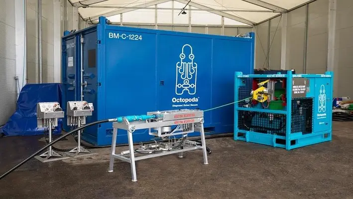
Expro, a leading provider of energy services, has successfully deployed its Octopoda annulus intervention system to restore annulus pressure integrity and return a well to production in Colombia.
The Octopoda system reached 300 meters in the annulus, a world record depth, and sealed the C annulus of the well ‒ thus removing the risk of casing collapse and gas migration to enable the well to produce and significantly extend its production lifespan.
Alistair Geddes, Expro's Chief Operating Officer, said, “Everyone at Expro is proud of this outstanding achievement and the team's extraordinary performance to reach new depths. Not only is it Expro's first venture into the Latin American market using the Octopoda system, but a world first.”
“Octopoda is already proving itself as an innovative and cost-effective solution for solving well integrity issues across the industry. It enables our customers to prolong their well lifespan, making it economically viable to regain production from shut-in wells.”
The value-added intervention operation was completed at a cost that was estimated to be approximately 25% less than the cost of a conventional workover rig-enabled repair and the operation resulted in significantly lower carbon emissions than the conventional alternative.
Octopoda removed the need for a heavy workover rig to allow controlled circulation of annular fluids and the installation of a resin plug at the external casing shoe depth. This successfully sealed the annulus and enabled production to be resumed from the wellbore.
Utilising a unique design, Octopoda is deployed on annulus inlets, removing workover rig requirements, offering an alternative that can be rapidly deployed across all types of installations, onshore and offshore, to maximise operational uptime while reducing overall HSE exposure.
“Expro’s recent success with Octopoda shows the capabilities of this truly unique technology and our ability to optimise and expand the life of the growing number of aging wells around the world,” Geddes added.
“Octopoda is the latest example of Expro’s commitment to investing in innovation, developing new technologies and working towards reducing our own and our clients’ carbon footprint.”
To best meet customer needs, you must be a solution provider, not just a product provider. Parker LORD’s attitude is, and has always been, to collaborate with customers to find an approach that meets their needs quickly and easily.
They have proven this mindset yet again by finding a better process for working with customers on gimbal assembly design.
Parker LORD gimbal pads and assemblies for offshore oil rigs and intervention vessels are designed under strict process and quality controls to ensure each part performs consistently. They can accurately and dynamically model the stiffness of any gimbal system in any plane of rotation. A step beyond competitors, this new tool incorporates feedback from customers in real time to create tailored solutions. The result is a product designed to handle extreme loading and environmental conditions for improved pad life.
The flexible design tool introduces a process unprecedented for the oil and gas industry, creating solutions through working closely with the customer, instead of only using existing catalog parts. Traditionally, the customer and supplier might have limited interaction during the ordering process. Using this flexible design tool, placing an order becomes a collaborative partnership where Parker LORD engineers and the customer work together to solve problems. Additionally, the tool can accommodate design changes dynamically, allowing for multiple design versions.
To make this work, the first things Parker LORD want to know about a customer’s gimbal assembly is how it is intended to be used, the range of expected limitations and the maximum stiffness needed. From there they work together to produce a solution.
In one example, this fast-moving live design process allowed them to identify, analyse and quote four different systems as the project scope changed over a three-week period. The customer was struggling with how to add a much-needed gimbal assembly to an existing bid and through these conversations they created a solution that was within budget.
The design tool allows system level rotational stiffness calculations in any direction. This graph below shows the relative pad positions and corresponding system rotational stiffness in each plane from center. Asymmetric, or non-uniform spacing can also be evaluated using this tool. ")
It takes innovation to work on a solution. Sometimes the solutions can involve renting a part instead of buying it or designing a part to specifications that will then bring it into budget. The market collapse is forcing rig and vessel operators to think differently. Flexibility and elegance around the design are now key.
Fill out this form and a member of Parker LORD’s engineering team will contact you to talk through how their flexible design tool can help you when ordering your next gimbal assembly.
Learn more about the new Parker LORD flexible design tool at https://www.lord.com/industries/oil-and-gas/offshore/drilling-rigs/gimbal-bearing-assemblies-and-pads
Page 100 of 122