This article is a direct result of inspiring presentations on a novel technology from the 2nd Annual Well Intervention Workshop for the Middle East in Abu Dhabi. What I picked up there, made me replace my scheduled article and write about the PWC® (Perforate, Wash, Cement) technology.
We have published two pieces of what was supposed to be a series of three posts on Plug & Abandonment. The first article focused on legislation and standards of design for P&As, and the second one discussed materials that meet the requirements to be used for P&As.
The third article was supposed to focus on deployment methods. In the meantime, I attended the forementioned Well Intervention Workshop; the presentations that I witnessed changed the original plan.
The event gathered specialists in well integrity from different oil and gas operators from the Middle East such as ADNOC, Aramco, Dragon Oil, Agiba, ADMA, and ONGC. These operators handle complicated wells from which they presented case studies. There were workshops on P&A, annulus pressure management and coiled tubing interventions. The latest technologies, like downhole video analytics, casing patches and well integrity in multi-lateral wells and extended reach wells, also had their fair share of attention.
From one of these sessions, I ran across a technology that is being extensively used by one of the operators in the UAE. The subject was so interesting that I decided to change the plans for the third P&A article and cover this technology instead.
Initially, the post was to evolve around cementing thru Coiled tubing (and maybe a little about dump bailors) as a deployment technique for P&As, since most of the conventional techniques are already covered in other articles on the blog. Besides, you can download the guideline for cement plugs, which address most, if not all, aspects of the conventional placement methods.
What we will do then is to go ahead with this article on the new technology and then leave for a fourth article to discuss coiled tubing cementing.
The article you are reading is co-written with Mr. Dave Ringrose, VP for the Middle East in Hydrawell intervention, the company behind the PWC® (Perforate, Wash, Cement) technology.
You may remember the discussion on the legislation and basis of design for P&As and how we discussed that the barriers should be set in front of a suitable caprock (impermeable, laterally continuous and with adequate strength and thickness) and overlap with annular cement. See figure 1 for more details.
For cased hole sections, casing alone is not considered a barrier to the lateral flow, due to the potential for casing leaks, but cemented casing could be sufficient “as long as there is sufficient confidence in the quantity and quality of the cement in the annulus.” What this means is: If a log is available, 100 ft of good cement will do. If no logs are available, then 1,000 ft of cement, using the theoretical top of cement as calculated by “differential pressures or monitored volumes during the original cement job,” would be required to allow for uncertainty.
When cement behind the casing is not good, the operators were forced to perforate-squeeze and, in some cases, mill out the casing completely to achieve proper zonal isolation across the wellbore. Here is where PWC® becomes a very interesting alternative.
PWC® is a single run assembly with these main parts:
-
- TCP perforating gun
- Internal cement foundation tool to support the cement in place
- A jetting tool that is used to condition the space behind the casing to receive the cement, called the Hydra-hemera.
- And the Hydra spray cementing valve and Hydra Archimedes cementing tool which work together to push the cement behind the casing and ensure proper coverage and bonding against tubulars and the wellbore.
According to Hydrawell records, PWC® has been used to set 215 annulus cement plugs in different areas round the world exceeding 97% success rate as measured by 15 different operators.
Click on picture for larger version
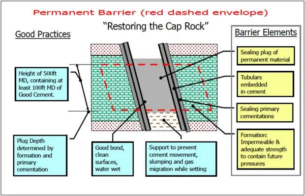
Figure 1. Source: Guidelines for the Abandonment of Wells, p12 (OGUK, 2015)
From the presentations delivered at OWI and the conversations held with Mr. Ringrose, I could summarize two keys aspects of the PWC® technology:
-
- Time-Saving
While the conventional method of section milling, under-reaming and then placing a cement plug typically takes ten days in a trouble-free operation (however, this method is prone to significant trouble time and can take significantly longer), the HydraWell method takes 2 – 4 days.
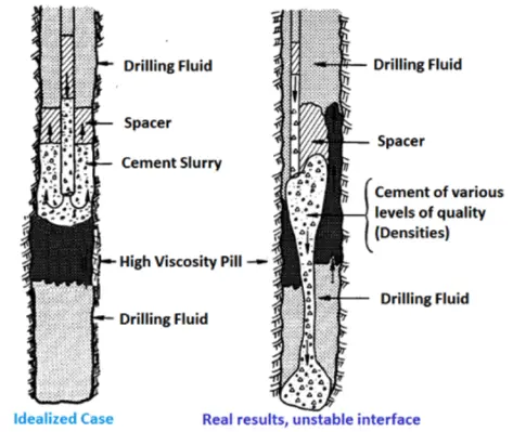
- Cement plug quality
Due to the effective annulus cleaning and cement placement technology, cement plug quality increases as displacement of wellbore fluids is enhanced, and impact of contamination is reduced. This technology also allows for plugs to be effectively set through two strings of casing -into two annuli- at the same time.
PWC® is not only valuable for wells requiring P&A interventions aiming at fulfilling the annulus barrier requirements in the UKOG guidelines; PWC® can also be useful in wells that are shut-in due to unbleedable annulus pressure in annulus B or C. The technique can provide a reliable method of placing annular barrier(s) -closer to the leak source- and returning these wells to production or injection.
Along the same line of thought, this deployment method can be utilized to repair “wet casing shoes” and achieve the required isolation – before drilling into the next zone after a poorly executed primary cement job. Or to allow the setting of a side-track whipstock across an uncemented (or poorly cemented) area, setting a casing exit support plug in the annulus.
WHAT ABOUT RESINS?
Needless to say, the capabilities of the tool left me and other delegates at the OWI convention astonished. A topic of discussion that came up during one of the presentations was the use of conventional cement versus micro-cement together with the PWC® tool. But then it wasn’t long before the conversation revolved around the combination of PWC® and resins as a mechanism of achieving deeper penetration and enhanced isolation behind the annulus.
Hydrawell partnered up in joint R&D studies with Wellcem to evaluate the use of resins through their PWC® tool to further enhance penetration into the annulus behind the casing. The solid- free resin offered by Wellcem can penetrate narrow cracks and channels where not even micro-cement can penetrate. The combination of the PWC® tool with resins is expected to enable operators to properly place isolation barriers even under the more challenging placement conditions.
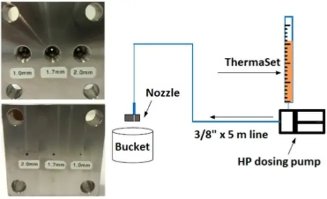
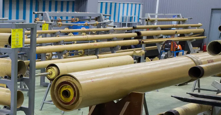
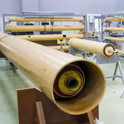
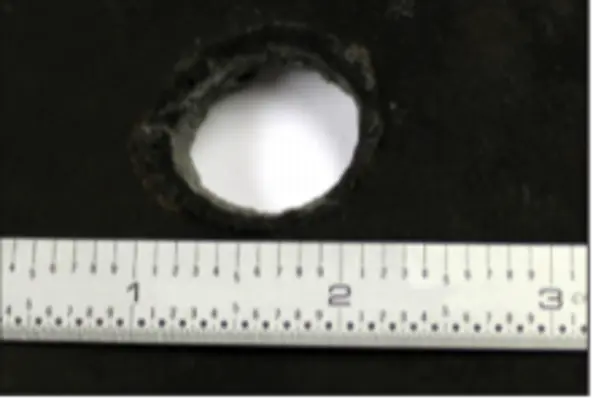
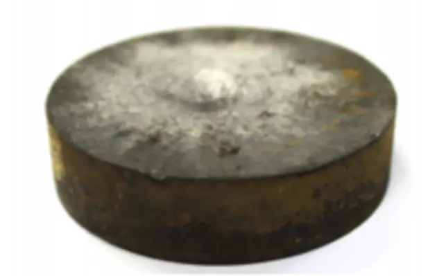
Figure 2. Test assembly for pumping the resin thru 1.7 mm nozzles.
In one of these studies, the objective was to verify the possibility of pumping high-density ThermaSet® (Wellcem polyester resin) through the ¼ inch nozzles in the HydraWash® tool under a certain allowable pressure at high pumping rates (several Bbl/min), see figure 2. To execute the test in a workshop environment, calculations were carried out to downscale the test parameters. A reduced size prototype nozzle with 1.7 mm opening and 5 litter/min flow rate (based on estimates) was considered the optimum settings for observing the pump pressure during the test.
Test results and observations confirmed that 2.3 SG (19.2 PPG) resin can be pumped through the 1.7mm nozzle at 5.0 litter/min with ~310 psi pressure differential -1,400 psi applied pressure- (Pressure losses in the nozzle with water were 280 psi in comparison).
Quality check of the samples taken before and after pumping showed similar results – leading to the conclusion that the nozzle size has no visible effect on the properties of the resin plug.
All in all, it seems like we should be up for some more exciting case histories from the combination of these two new technologies used in an environment that would have been too hard for conventional methods to succeed.
We’ll leave it here – stay tuned for our next piece on Coiled Tubing Cementing, which will complete this series on P&A operations.
Gracias!
Click on this link to see an animation of the PWC® single run assembly
MIGUEL DIAZ/DAVE RINGROSE

Miguel Diaz is Wellcem’s Business Development Manager for the Middle East and North Africa region. He has 20 years’ experience from operations, technical advisor, quality assurance, business development and management positions in the oil & gas industry from all areas of the high-pressure pumping services. Dave Ringrose has 40 years varied experience in drilling management, drilling engineering, drilling operations and project and operational support work. He is highly experienced in all aspects of drilling and workover management and currently responsible for all HydraWell operations and business development in the Middle East


![[Free eBook] Guidelines for setting Cement Plugs](https://cdn2.hubspot.net/hubfs/2922560/hub_generated/resized/6564f313-ade6-4ad5-ba0d-1ab08f43e101.png)