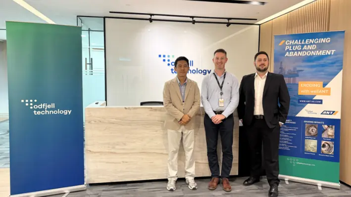
Well integrity and production optimisation specialist Coretrax has strengthened its portfolio after acquiring a complementary suite of well intervention technology from Wireline Drilling Technologies.
The significant investment has expanded Coretrax’s offering. Since completing the acquisition, the firm has signed a global route to market agreement with a supermajor to support its well intervention requirements internationally and secured additional work in the Middle East with an existing client.
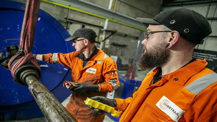
The company has already integrated the new assets and software, which include wireline pump units, drilling units and tractor modules into its existing technology portfolio. The additional equipment boosts Coretrax’s current well integrity offering, enabling the business to access and address damaged wellbores, and support highly deviated wells more efficiently.
John Fraser, CEO at Coretrax, said, “This investment demonstrates our continued drive to enhance and improve our services, positioning Coretrax as a full turnkey solution for
all wellbore entry and remediation operations. The additional technologies have integrated seamlessly into our portfolio of tools and are supporting several new contracts including a global supermajor and an ongoing long-term project in the Middle East.
“As the industry remains focused on extracting maximum recovery from existing wells, demand for wireline applications has increased as operators realise the cost and sustainability
benefits they bring across well intervention, frac plug drilling, well conveyancing and lateral drilling. Our recent investment will undoubtedly open up new markets for the business and we are excited about the opportunities this will bring.”
Plexus Holdings, an oil and gas engineering services business, has completed an agreement with SLB, a global technology company driving energy innovation for a balanced planet, to replace their existing surface production wellhead licence.
The new licence has a wider field of use for a cash consideration of US$5.2mn. It will provide SLB a perpetual royalty free licence for Plexus’ POS-GRIP technology and HG seal technology along with any improvements or derivates to the technology for surface wellhead production applications. The scope of this includes oil and gas production and storage applications, CO2 storage, hydrogen storage and water and cuttings reinjection.
In addition, the agreement includes a non-exclusive licence to SLB for Adjustable Surface Production Wellheads, and HG Trees with the potential to generate royalties for Plexus from such special applications of the POS-GRIP technology.
"SLB's leading technology position will be further enhanced by this new technology, providing our customers with additional rig time savings through ease of installation and enhanced seal integrity assurance for onshore and offshore applications, commented Badri Mani, Director of Surface Production Systems, SLB. “We are very excited about the prospects for this technology."
According to Plexus, the combination of its technology with SLB’s manufacturing quality, technical expertise, innovation and global support structure will ultimately bring value and efficiency to operators across the globe.
Ben van Bilderbeek, CEO of Plexus, added, “This new licence agreement is a further validation of Plexus' IP by this leading energy technology company and recognises the contribution our leak-proof POS-GRIP wellhead equipment can make to the oil and gas industry's ESG and NetZero goals. Not only does the agreement further reinforce our growing relationship with SLB, but it also enables Plexus to continue to operate in the surface production wellhead sector on a limited basis, whilst focusing on the 'preventative' aspects of POS-GRIP metal seal technology."
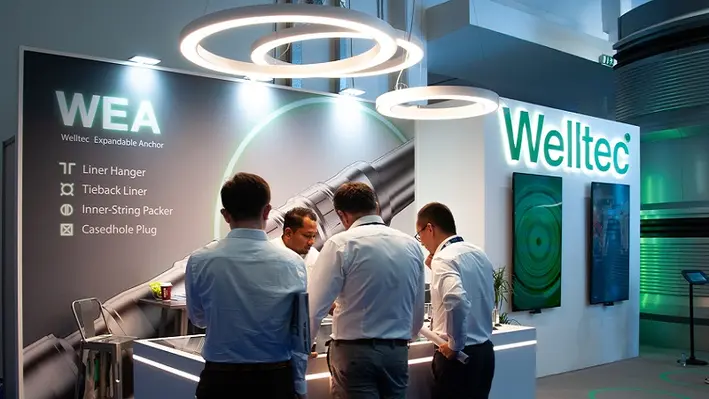
Welltec sees great prospects in the Middle East for its recently launched Welltec Expandable Anchor (WEA).
The Welltec Expandable Anchor (WEA) was a key focus at the company’s stand at ADIPEC 2023, where Completion, Intervention, and New Energy & Climate Technology solutions were showcased, all with optimisation and efficiency as core design principles.
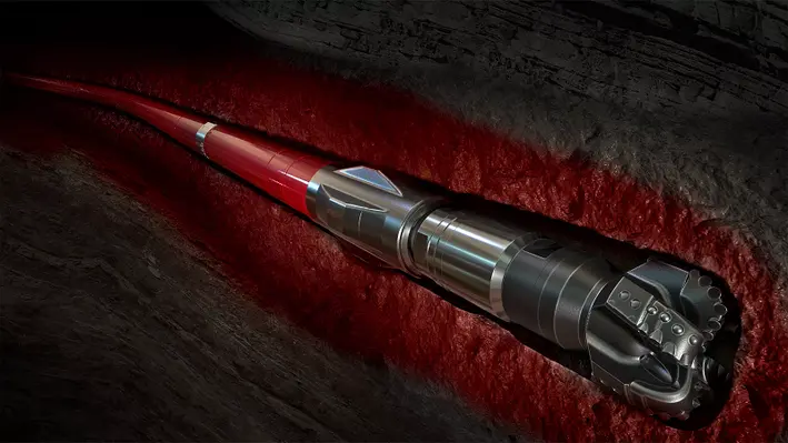
Engineered and rigorously tested over the past couple of years, the WEA is a 4-in-1 life-of-well completion system for anchoring in cased hole. Firmly rooted in proven metal expandable packer technology, it provides industry-leading reliability, efficiency, and flexibility, as explained by Kevin Wood, Sales Director for Completions in the Middle East.
“The WEA has three key benefits. It is reliable, with essentially no moving parts; it’s basically a metal expandable sleeve that is secured onto a casing. It is efficient, as it is slimline and full bore, so operators can circulate fluids or cement at high rates compared to other products. It can also be rotated when run in hole making for efficient installation in deviated and challenging wells. And it is flexible; one particular size of WEA can cover multiple casing grades and we can also add or take away modular parts, depending on the environment in the well.”
The product is available in a full range of sizes, with key completion applications as a liner hanger, tieback liner, inner-string packer, and casedhole plug. All versions of the product are qualified to the API 19LH V1 standard and are fully compatible with Welltec’s Metal Expandable Packer (MEP) portfolio.
The WEA clearly addresses a market need, as illustrated by several installations taking place immediately after qualification, with a requirement from one Middle East operator for product delivery within eight weeks. Facilitated by its in-house design and manufacturing capabilities, Welltec was able to deliver the solution in seven weeks.
Prospects in the region are very encouraging, Wood said, “ADIPEC has been big for us; we signed a two-year call-off contract with ADNOC Onshore for the WEA technology which can address several of the challenges they face on some wells.
“The products covered under the call-off agreement are for the prevention of sustained casing pressure – this is annular casing pressure that can makes its way back to surface, a challenge which has cost the industry around US$75bn since 2009,” he continued. “Around 35% of wells globally exhibit gas pressure in the annulus, and the only way to deal with that is to flare it off, or vent it off, both of which are harmful to the environment. That’s where this anchor and our technology come in. It’s a life-of-well solution, providing a barrier in the well. It’s important that when a well comes to the end of its life, it is decommissioned correctly. The problem with cement is that over the life of the well it expands and contracts, which creates leaks through the cement. Using the Welltec Annular Barrier, which the anchor is incorporated with, gives you a fully qualified barrier that you can abandon above, thereby future-proofing the well for abandonment.”
This in effect helps reduce emissions. The emissions reduction angle certainly chimes with ADIPEC’s central theme of decarbonisation. Wood stressed the company’s commitment to the energy transition, which is “in our DNA – it’s not just a buzzword for us”. He explained that Welltec is playing a key role in Project Greensand, which involves the long-term storage of CO2 by injecting it into depleted reservoirs in Denmark. To support this, and similar projects, Welltec’s New Energy & Climate Technology segment has already constructed an advanced testing facility in Denmark that enables full-scale downhole components to be tested against real-world CO2 well-type environments including high pressures, temperatures, and flow rates.
“The test loop and background to Project Greensand have opened up a lot of conversations here, especially with COP28 coming up,” he said.
Elsewhere in the Middle East, Welltec is active in Qatar and Saudi Arabia, the latter of which provides a manufacturing hub supporting regional activity, and keeping lead times to a minimum. Wood commented that this has been a “huge success”, and expansion of the hub is on the cards. “We can not only deliver quickly compared to our peers, we can also manufacture in the region.”
As far as future product development goes, Welltec has a couple of technologies in the field-trial phase. One is the Isealate Springblade Patch, a unique relining and repair solution for downhole applications. The first in-field deployment successfully took place in Europe in October.
“We also provide a service that can radially expand an existing casing string: the Saturn Expander. This can be utilised in wells where there is casing pressure,” said Wood.
“It expands the casing, compresses the cement on the outside, and cures any microannuli or leaks you might have.
“These solutions are coming to fruition now, and there is a lot of interest in the region, particularly given that many wells here suffer from casing pressure.”
Halliburton has introduced the BaraFLC Nano-1 wellbore sealant, a nanocomposite suspension that boosts wellbore stability.
The new sealant works with Halliburton’s existing conventional and high-performance water-based fluid systems to create a tighter, more secure seal that decreases fluid loss into the formation. It uses nanoparticles to reduce interaction between filtrate and reactive shale formations, preventing pore pressure transmission. This helps strengthen wellbore integrity.
“In many areas around the world, our customers require high-performance water-based fluid systems to maximise the value of their wellbore,” said Toby Dixon, Senior Vice President, Halliburton Baroid. “We developed nanotechnology that results in a step change compared to conventional sealants and rivals the performance of oil-based fluids.”
Sold as a liquid, BaraFLC Nano-1 sealant reduces bag waste and airborne dust. It comes in ready-to-inject form and easily mixes with water-based fluids, which can reduce non-productive time.
BaraFLC Nano-1 was used in Oman, where it reduced dilution rates, lowered fluid viscosity, and tightened filtration rates during a 22-day interval with maximum downhole temperature >300ºF.
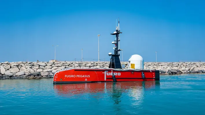
Fugro, a leading geo-data specialist and surveying services company, has completed the Middle East’s first remotely operated subsea inspection using a low-carbon emission unscrewed surface vessel (USV).
The company deployed the Fugro Pegasus USV (which is part of the Blue Essence fleet, built by SEA-KIT International) to perform site survey and inspection services on an offshore gas platform offshore UAE for operator Atlantis, ahead of its forthcoming decommissioning programme.
Fugro conducted the operation from its onshore remote operations centre (ROC) in Dubai, using a specialist team of mariners and surveyors to perform the subsea work on the UAQ3 platform within the Umm Al Quwain gas field. The Fugro Pegasus USV was equipped with a Blue Volta electric remotely operated vehicle which was used to inspect the integrity of the platform’s structure. It also generated a detailed map of the surrounding seabed.
All of this was streamlined to the ROC where it was reviewed in real-time during the operation. This data enabled the team to identify and investigate areas of further interest in the delivery of a comprehensive risk assessment for the client.
The economical design and optimised fuel systems of the company’s USVs eliminate 95% of carbon emissions against conventional vessels. This also allows them to remain at sea for up to two weeks without refuelling.
Patrick Boyce, Drilling Manager at Atlantis (UAQ), commented, “Fugro’s remote survey technology aligned seamlessly with our projects HSEQ, technical goals and was the most attractive commercial choice. The Fugro Pegasus was able to mobilise on time and despite difficult sea conditions, it completed the full scope of work in 40% of the allotted time frame. The USV operation was managed by the technical team at the very impressive Fugro ROC. Communications with the USV were strong throughout and provided excellent imaging results. Of particular note was the evident expertise and professionalism of the Fugro team, who have obviously dedicated many months to honing their execution procedures.”
Hannes Swiegers, Fugro’s Director of IRM Services & Remote Operations for the Middle East and India, surmised, “This is a significant milestone for our Middle East business and demonstrates how novel technologies can play a key part in delivering our clients’ long-term safety, sustainability and in-country value ambitions. Together with our clients, we are setting a new standard in geo-data acquisition and analysis through continuous innovation, reducing time, risk and carbon emissions. This new era of remote and autonomous technology will define the future of offshore operations in the energy sector and contribute towards a safer and more sustainable world.”
SLB, a global technology company, has released its Q2 2023 results revealing the part intervention and stimulation activities are playing in the business growth.
The company reported a revenue of US$8.1bn, representing a 20% increase year-on-year. SLB CEO Olivier Le Peuch commented, “I am very pleased with our second-quarter results, which reflect significant growth in the international markets, particularly in the Middle East & Asia, and offshore. North America revenue also grew sequentially benefiting from our agility across the most resilient basins and market segments, although the rig count in the area declined. As the upcycle continues to unfold, we are excited about the opportunities for our business, with international- and offshore-led growth fueling strong pretax segment operating margin expansion and cash flows as highlighted in this quarter’s results.
“Compared to the same period a year ago, international revenue grew 21%, outpacing North America which increased 14%. Year on year, revenue grew 20% and pretax segment operating margin expanded 240 basis points (bps), representing the tenth straight quarter that we have increased our pretax segment operating margin year on year. This was driven by the international markets, where we posted our highest year-on-year incremental margin in the last three years, demonstrating the earnings power of our operations in these markets.”
Breaking this down, the company noted that reservoir performance revenue grew 9% sequentially due, primarily, to increased intervention, stimulation and evaluation activity internationally. Profitability improved mainly due to higher activity and improved operating leverage across intervention and stimulation with new technology deployment contributing to margin expansion, particularly in Saudia Arabia, Qatar, Europe & Africa and Mexico.
The Middle East & Asia was a particularly strong-performing region for the company with a 10% increase sequentially driven by double-digit revenue growth in Saudi Arabia, Egypt, UAE, Kuwait, China and India. SLB attributed to higher drilling, intervention, stimulation and evaluation activity here, both on land and offshore. Saudi Arabia was a particular hotspot for higher stimulation and intervention activity. Reservoir Performance grew 23% year-on-year, primarily down to higher intervention and stimulation activity led by the Middle East & Asia.
The company also highlighted how it had experienced increased intervention and stimulation activity in Argentina which helped offset the lower revenue recorded in Mexico.

Aquaterra Energy, a leader in global offshore engineering solutions, has announced a multi-million-pound contract with a major Abu Dhabi based operator, working in partnership with TPMC, to provide offshore riser equipment and services for a decommissioning campaign offshore Abu Dhabi.
Aquaterra Energy will provide a completion and workover riser system complete with AQC-CW connectors, as well as an additional subsea riser system, tieback engineering and rig modifications. It will do this to decommission eight wells, in 80 m water depths by 2029. Throughout the contract Aquaterra will deliver a complete end-to-end managed service, providing engineering services, expertise and personnel.
The completion and workover riser system, complete with AQC-CW connectors, is certified to BS EN ISO 13628-7 2006 and can operate in water depths of up to 1,500 m. The system has been designed to withstand repeat make and breaks, whilst offering a gas tight metal-to-metal seal.
Aquaterra Energy will work closely alongside in-country partners to manufacture and transport the project equipment. Local in-country inspectors will be deployed to ensure the high quality of work throughout the project.
James Larnder, Managing Director, Aquaterra Energy, remarked, “We are delighted to have secured this work in the Middle East and to expand on our decommissioning and riser expertise. This is an important region for us as a business and we’ve seen significant growth here over the last few years. We plan to continue this momentum and are on course to increase both our presence and revenue in the region by the end of the year. This project represents a step forward in this journey as we spearhead our global expansion.”
Andrew McDowell, Operations Director at Aquaterra Energy, added, “Winning this tender further demonstrates our team’s global riser system expertise, understanding of operational requirements in the Middle East, and the significant advantages of our independent connector OEM status. We’re looking forward to utilising our experience and working closely alongside engineers in the UAE, sharing our knowledge, and building on existing local capabilities to deliver a top-class end-to-end service.”
After identifying the Middle East as a key geography to support its global growth plan, the contract marks another significant step forward in the region for Aquaterra Energy. It has now delivered intelligent engineering solutions to more than 35 projects in the Middle East to date.

TGT Diagnostics, a through-barrier diagnostics company for energy production and storage, has launched its latest acoustic platform, ChorusX, a new diagnostic resource specifically designed to locate and characterise flow in oil and gas wells.
This all-new acoustic array platform enables energy companies to find and map fluid flow throughout the well-reservoir system with greater ease and precision, helping them to keep wells safe, clean, and productive.
Ken Feather, TGT’s Chief Marketing Officer, commented, “Understanding flow dynamics in the well system is the key to unlocking better well and reservoir performance, and acoustic techniques have become an indispensable means of achieving that goal. ChorusX is the result of two decades of intensive research, innovation, and extensive field experience in applying the power of sound to flow diagnostics in thousands of wells. Eight high-definition array sensors, extreme dynamic range recording and a unique phase analysis engine work in concert to deliver uncompromising levels of clarity, precision, and certainty to analysts and well operators.”
At the heart of ChorusX is a compact array of eight nano-synchronised sensors that record high-resolution flow sounds across an extreme dynamic range of intensities and frequencies. A unique phase analysis workflow combines specialised acoustic field modelling with a sophisticated waveform-matching algorithm. This combination delivers an important new dimension to acoustics and flow diagnosis – radial distance. In combination, these advances underpin four new complementary answer products that enable TGT analysts to easily and accurately locate and map flow throughout the well system.
Ken added, “ChorusX has been redesigned from the ground up to excel in three important areas: extending spatial and audible reach to record the lightest, quietest, and furthest flows; recognising different types of flows; and pinpointing flow sources with unmatched accuracy in depth, and radially. Flow events are displayed more clearly in high definition, enabling operators to plan actions with greater confidence and implement them efficiently with precision.”
ChorusX is available to all TGT Diagnostics customers through a range of True Flow and True Integrity/Seal Integrity products.
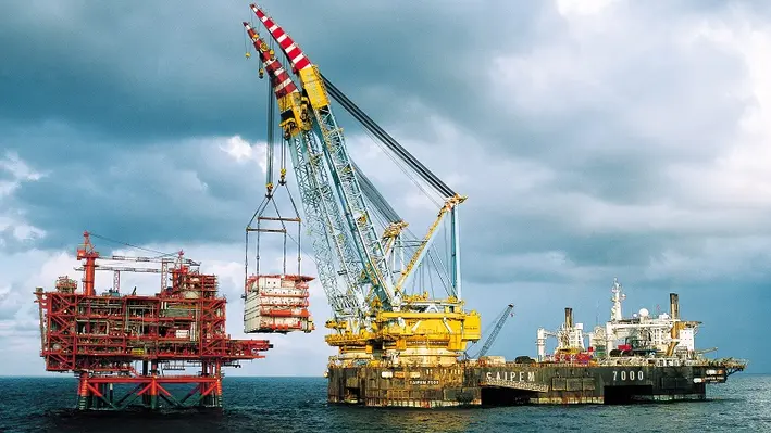
Saipem has been awarded two new offshore contracts, one for an Engineering, Procurement, Construction and Installation (EPCI) project in the Black Sea and one for decommissioning activities in the North Sea, with the total value amounting to approximately US$850mn.
The first contract was assigned by Turkish Petroleum OTC for the second phase of the Sakarya FEED and EPCI Project, and entails the engineering, procurement, construction and installation of a 16” pipeline, 175 km long at 2,200 m water depth in the Turkish Black Sea Waters. The offshore operation will begin in summer 2024 and will be conducted by Saipem’s flagship vessel, Castorone.
The other contract has been assigned by EnQuest Heather Ltd. for the decommissioning of the existing Thistle A Platform located in the UK sector of the North Sea. Saipem’s activities will include the engineering, preparation, removal and disposal of the jacket and topsides, with possible extension to further subsea facilities. The services will be carried out by the Saipem 7000, one of the largest semi-submersible heavy-lifting vessels currently in the world.
Fabrizio Botta, Saipem Chief Commercial Officer, said, “These important awards demonstrate Saipem’s excellent competitive positioning in the Offshore Engineering & Construction market a sector that is experiencing a full expansion momentum of which Saipem is ready to seize the opportunities.
“The contract awarded in the Black Sea is a confirmation of Siapem’s prominent positioning and of its long-standing relationship with the clients. The North Sea contract, finally, is a further example of Saipem’s capabilities in a segment where the combination of innovative engineering, unique assets and safe operations is crucial.”
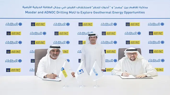
ADNOC Drilling Company has signed a five-year Memorandum of Understanding (MoU) with Masdar, one of the world’s leading clean energy companies, for the collaboration around development, investment, operations and projects to responsibly advance the energy transition.
Under the MoU, the company will engage as a drilling technical expert and advisor to support Masdar’s deployment of geothermal energy around the world. The companies will jointly evaluate the potential for ADNOC Drilling to provide geothermal drilling services.
Chief Executive Office for ADNOC Drilling, Abdulrahman Abdulla Al Seari, said, “Geothermal energy has enormous global potential and energy developers are challenged to ensure smart and innovative ways to deliver cost-effective wells. Our leading integrated drilling services offering can bring advanced, efficient start-to-finish drilling and completion technologies to enable Masdar the potential to generate clean geothermal energy to cool thousands of homes and office buildings.”
Mohamed Jameel Al Ramahi, Chief Executive Officer at Masdar, commented, “This MoU with ADNOC Drilling further reinforces Masdar’s commitment to unlocking clean energy opportunities across a wide range of technologies. With Masdar recently adding geothermal energy to our growing clean energy portfolio, we are excited about the important role that geothermal can play in helping to drive forward the global energy transition, and we look forward to working with ADNOC Drilling to realise that potential.”
Masdar entered the geothermal energy sector last month, with a strategic investment in Indonesia’s Pertamina Geothermal Energy (PGE), one of the world’s largest geothermal players.

This year’s OWI Middle East and North Africa (OWI MENA 2023) conference promises to be grand affair as sights are set to broaden the format and shine the spotlight towards operators in the Gulf and North Africa equally.
With the tagline of this year’s conference being ‘future-proof your intervention projects to exceed environmental targets and optimise well programmes by utilising transformative digital and downhole technologies’, OWI MENA is the only place to offer key learnings to the well intervention community in order to the build the best roadmap for future growth.
Constantly evolving and growing, OWI MENA 2023 boasts the largest roster of speakers to date, with 20 operator speakers set to lead discussions on key topics such as market status, sustainable well programmes, well integrity, innovative technologies and end of life. Speakers include representatives from ADNOC, Shell, bp, Aramco, and many more.
After taking on board client feedback, there is a huge appetite within the community to hear from North African operators, and this year there is a dedicated spotlight session for the region. OWI MENA 2023 will also exhibit two networking sessions, three breakout workshops and more than 12 demos in the Innovative Technology Showcase Hall in order to further promote collaboration between delegates. 40% of attendance will be from major, independent or national operators, as well as 35 % from expert technology providers, meaning there is ample opportunity to expand individual networks.
For more information and session details, the full brochure can be downloaded here. Any questions regarding the conference please reach out to Rachael Brand at

Saipem, an advanced technological and engineering platform for the design, construction and operation of infrastructures and plants, has worked with MCS, an underwater technical and digital solutions company, to launch a new asset integrity management system.
As per the announcement on social media, ‘The PALM Suite’ (which stands for Platform for Asset Lean Management) is designed to support offshore energy operators with asset data management, risk assessment and inspections planning of offshore infrastructure across oil and gas, renewables, power and data networks.
According to Saipem, The PALM Suite unlock a new layer of service-oriented capabilities and leverages advanced features such as 3D reconstruction for subsea dimensional control and IoT data gathering. The collaboration brings together Saipem’s extended asset integrity expertise and subsea robotics portfolio with MCS’ data science and software competencies.
Page 8 of 13
Copyright © 2026 Offshore Network