- Region:
Middle East
- Topics:
All Topics, Integrity
- Date:
Jun, 2019
In this second part of my article series on SCP, I will discuss how to define whether you have an SCP scenario that needs intervention or not. In the first article in this series, I talked about a framework from which we can deal with the problems related to SCP. I also gave an overview of which guidelines from different industry bodies that address this topic.
Following the advice given by these guidelines and listening to what operators in the Middle East are telling us, I suggest you look into four aspects of your well annulus behaviour to define whether you have an SCP scenario that needs intervention or not:
Leak nature
Leak rate
Annulus pressure
In a less conventional manner; hydrocarbon gas mass.
LEAK NATURE
There may be a risk of introduction of toxic material such as H2S or radioactive agents into the annuli through the SCP. Such materials imply a considerable risk to personnel safety, and their presence, no matter the other parameters, indicate that the leak needs to be remediated.
LEAK RATE
Excessive leak rates increase the consequences if containment is lost. The magnitude of the leak will dictate the operator’s ability to normalize the situation since it defines the amount of energy released, its impact on the affected area, and in general, the leak escalation potential. So while a significant leak needs immediate attention, there is a value at which it doesn’t.
API RP 14B states acceptance criteria for leakage rate through a closed subsurface safety valve system, and although the norm is not directly applicable for SCP, its reasoning may still be regarded as an appropriate analogy for determining acceptance criteria for SCP. OGN117 use it as its acceptance criteria for annulus leaks.
The acceptance criteria for leak rate, when hydrocarbons are present in the source of influx, are:
15 scf/min (0.42m3/min) for gas
0.4 liter/min for liquid
ANNULUS PRESSURE
What sounds like a reasonable and empiric statement anywhere you hear it is that the pressure in the annulus should never reach the maximum allowable annulus surface pressure at the wellhead (MAASP). However, in this regard, OGN 117 only advise operators to take into consideration all aspects that detrimentally affect the normal rating of the wellbore hardware when setting the MAASP.
Instead, API-90 (Offshore wells) goes into detail on how to establish an acceptable level of risk for annular casing pressure, using two parameters.
First, sustained annular casing pressure that is greater than 100 psig must bleed to zero psig. If it does, it indicates that the leak rate is small and the barriers to flow are still effective. Second, a procedure is offered to calculate a Maximum Allowable Wellhead Operating Pressure (MAWOP) which sums up to:
MAWOP is based on Minimum Internal Yield Pressure (MIYP) of both tubulars (the one being evaluated and the next outer one) as well as the Minimum Collapse Pressure (MCP) for the inner tubular which are calculated according to API Bulletin 5C3.
MAWOP for an annulus is expected to be less than the following:
50% of the Minimum Internal Yield Pressure (MIYP) of casing string being evaluated; or
80% of the MIYP of the next outer casing; or
75% of the Minimum Collapse Pressure of the inner tubular pipe body o In case of the outer most pressure containing casing, the MAWOP can’t exceed 30% of its MIYP
If there is pressure communication between two or more outer casing annuli (e.g., communication between the “B” and “C” annuli or between the “C” and “D” annuli, etc.), then the casing separating these annuli is not considered a competent barrier and should not be used in the MAWOP calculation.
Figure 3 shows an example of MAWOP calculations, note the MAWOP is controlled by MIYP of the next outer casing for the “B” annulus, while the MIYP pressure of the casing being evaluated dictates the MAWOP of the annulus “A” and “C”. Finally, annulus “D” MWAOP is set by the MYIP of the outer most casing rule.
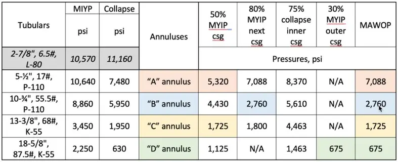
Figure 3. Example of MAWOP calculations for a well with no communication between annuli as per API-90.
Finally, API-90-2 incorporated two alternative cases with a slight deviation in the MAWOP calculations. The first one, called the “Default Designation Method” (DDM), does not require data or analysis to be applied. It can be used in a vast majority of onshore wells where poor data is available. It’s the least precise of the methods, and it’s appropriate for wells that operate at low levels of annular pressure. In the DDM, the MAWOP for the annulus being evaluated is 100 psi (700 kPa) for the outermost annulus, and 200 psi (1400 kPa) for all other annuli, and it requires no further calculations.
If a casing string has significant drill string wear, suspected or known erosion or corrosion, or is operating under high temperature, API-90-2 suggest a second deviation to API-90 for the calculation of MAWOP. This is called “Explicit De-rating Method” (EDM); in this alternative method, the operator would apply a specific reduction in the wall thickness or material properties in calculating the MIYP and MCP.
Using the EDM approach for the inner and outer tubulars, the tubular de-rating component of MAWOP for the annulus being evaluated is the minimum of one of the following:
80 % of the adjusted MIYP of the outer tubular string
80 % of the adjusted MCP of the inner tubular string
100 % of the adjusted MIYP of the next outer tubular string (provides an additional factor of safety)
100 % of the adjusted MCP of the outer tubular string, (i.e., the inner tubular of the next outer adjacent annulus)
The MIYP and the MCP for the tubing and casing strings can be calculated per API 5C3, but their adjusted values are calculated by the following:
MIYPAdj = [(MIYP ⋅ UFb) – ΔPwcd] and MCPAdj = [(MCP ⋅ UFc) – ΔPwcd]
Where MIYP and MCP are the minimum internal yield and collapse pressures; UFb and UFc are the burst and collapse utilization factors (1.0 equals 100 %); ΔPwcd is the pressure differential from the inside to the outside of the casing at worst case depth (i.e., the depth that yields the maximum ΔP). There is no industry standard for the utilization factors, and operators would choose them as part of their safety factors assumptions.
HYDROCARBON GAS MASS
An aspect often overlooked in the Middle East, and not covered by API, but well defined in the Norwegian sector of the North-Sea, is the mass of gas which will result in limited consequences and as low as reasonably practicable probability of escalation if released (OGN 117). Although not directly applicable to SCP, NORSOK S-001 Technical Safety contains an analog requirement to determine acceptance criteria for hydrocarbon gas mass:
“…For pressure vessels and piping segments without a depressurizing system, containing gas or unstabilized oil with high gas/oil-ratio, the maximum containment should be considerably lower than 1000kg…”
This item is typically ignored in the Gulf region as all tubulars have cement to surface either as part of their primary cement jobs or as a result of top-up jobs done afterward. So typically, the SCP leak paths are through cracks/channels in the cement sheet and/or micro-annuli between the cement and the casings. Therefore, the mass of hydrocarbon in the annulus tends to be below any known pre-set criteria. However, for those of you out there trying to come up with a set of criteria for your wells, this is an item worth keeping in mind.
We’ll leave it here for now, next articles will be around how to characterize the SCP to establish when an intervention is required, choosing the ideal solution and how to evaluate the success of any potential treatment.
MIGUEL DIAZ

Miguel has 20 years’ experience from operations, technical advisor, quality assurance, business development and management positions in the oil & gas industry from all areas of the high-pressure pumping services. He has worked in South America, the Caribbean Sea, central and eastern Europe, Sub-Sahara Africa and the middle east. Miguel serves as one of our cementing experts and is our Regional Manager for the Middle East and North Africa region.