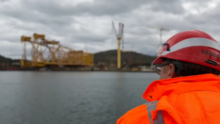
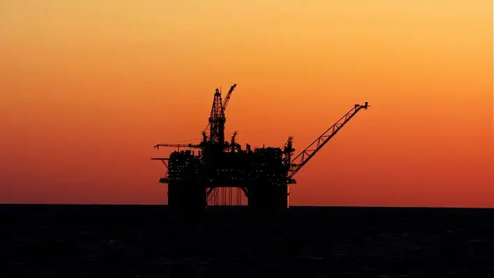
Helix Energy Solutions’ Q7000 vessel has berthed in Port Taranaki to carry out a crew exchange and load up on supplies before heading to complete the third stage of the Tui oil field decommissioning campaign, which is set to take approximately three months to complete.
Port Taranaki’s head of commercial, Ross Dingle, said the port was pleased to support the project, having also provided berthing services and laydown facilities for the first two stages.
Port Taranaki is working with New Plymouth-headquartered energy consultancy, Elemental Group, which is providing project management assistance of New Zealand operations for Helix Energy Solutions.
Nick Jackson, Elemental Group Director, said, “All up, there will be a team of more than 100 on the Q7000, over half being Kiwis and Aussies in operations roles working alongside the Helix crews, as well as several specialist roles, such as wireline and cementing.
“We’re excited to be a part of the project. I worked on some of the original Tui exploration wells, so it’s nice to be involved in restoring the mauri of the area.”
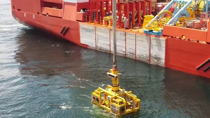
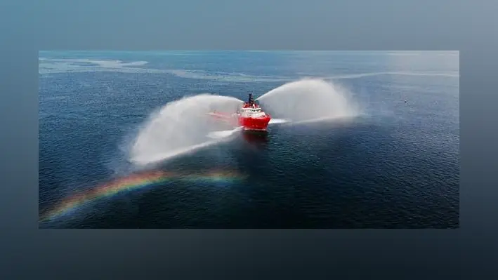
C-Innovation (C-I), an affiliate of Edison Chouest Offshore (ECO) and its family of companies, has announced the completion of its 46th well intervention in the Gulf of Mexico.
C-I, a leader in providing turnkey intervention services for the global subsea industry, also successfully completed three new riserless zone perforations, an industry first in both deepwater and high-pressure operations. The well intervention programme provides increased efficiency along with faster response times for emergent situations through the quick mobilisation and deployment of a vessel. C-I specialises in downhole operations, including production injection and integrity logging, caliper measurements, and setting water shut-off and zone bypass plugs. With more well intervention operations planned for 2023, C-I has played a pivotal role in increasing output for operators in the Gulf of Mexico.
George Wilson, Riserless Light Well Intervention Project Manager, C-I, said, “We are very proud to be a part of increasing oil production in this challenging geo-political climate. Riserless interventions on vessels offer both time and cost advantages over riser interventions. C-I’s programme offers the added benefit of dedicated dock space with advanced fluid tracking for faster between-well maintenance.”
C-I’s well intervention programme, which made its debut in 2017, has performed 31 hydraulic interventions and 15 mechanical interventions. The mechanical interventions included a total of 85 successful wireline runs, both e-line and slickline. C-I recently completed its longest mechanical intervention on board the vessel, Island Venture. With 79 days offshore, the operation included 22 e-line and slickline runs, as well as 22,205 barrels of fluid pumped into the well.
Wilson added, “C-I is a fully integrated service provider for our clients. Our turnkey solutions for well interventions alleviate the hassle of coordinating and managing the multitude of subcontractors needed to address complex jobs."
Researchers at the University of California, Davis, have suggested the cost of permanently plugging and abandoning the inactive oil and gas wells across the waters near Alabama, Louisiana and Texas could be upwards of US$30bn.
A paper released in the Nature Energy journal stated the area is home to 14,000 inactive wells that have not produced for five years and are unlikely to be reactivated in the region that has become the epicentre of US offshore oil and gas operations.
Leaks from wells closer to shore are more likely to damage ecosystems and release GHG emissions compared to deepwater wells. Studies have found that more than 90% of inactive wells are in shallow waters, and the costs to perform P&A services on those alone would be US$7.6bn.
The findings could help states makes decisions regarding their clean-up priorities, especially as US$4.7bn in federal funding has been authorised by the Infrastructure Investment and Jobs Act.
Liability falls to prior owners to plug and abandon wells in federal waters if the current owners become insolvent and are unable to cover costs. Large US oil companies currently own or have previously owned 88% of the wells in federal Gulf of Mexico waters and would legally shoulder the P&A liabilities.
However, in individual state waters, each jurisdiction handles liability differently, and prior ownership isn’t relevant. States oversee plugging programmes for orphaned wells whose owners have claimed bankruptcy.
“The bulk of the cost comes from plugging wells in deeper water where the environmental consequences are less than for shallow wells closer to shore,” said Mark Agerton, an Assistant Professor at UC Davis and lead author of the paper published.
“That money is probably better spent on state waters where they can’t go after prior owners for clean-up costs and it’s going to be a cheaper clean-up job with more environmental benefit.”
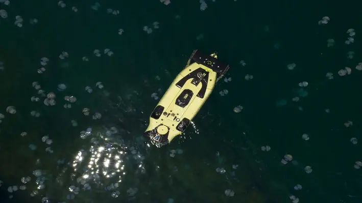
Saipem has been crowned the winner of the 2023 Spotlight on New Technology Award by Offshore Technology Conference (OTC) for its FlatFish Autonomous Underwater Inspection Drone.
The award is assigned by OTC for those who revolutionise the future of offshore energy through technological advancement and innovation. For this year’s Spotlight on New Technology award, Saipem was among the 15 technologies and 13 companies selected from around the world. The winners are selected against five key criteria: the technology’s novelty in the marketplace, innovativeness, demonstrated success, broad commercial appeal, and ability to make a significant impact across the offshore community.
FlatFish is an advanced underwater inspection drone which aims to inspect and monitor complex subsea infrastructures in an innovative and safe manner, from shallow waters down to 3,000mwd. The drone features an advanced AI-based control system and navigation features combined with state-of-the-art inspection capabilities which have been demonstrated in a deepwater pilot project executed at almost 1,800mwd offshore Brazil with the support of Shell Brasil, Saipem, Senai CIMATEC and Petrobras.
FlatFish is also part of the Hydrone platform, a ground-breaking subsea robotics programme conceived to support remote, vessel-free operations in order to reduce costs, risks and environmental impact of offshore operations, boasting 90% fewer CO2 emissions compared to conventional ROV services.
Mauro Piasere, Chief Operating Officer of Saipem’s Robotics and Industrialised Solutions Business Line, said, “This prestigious award is a testament to Saipem’s commitment to the development of cutting-edge solutions for the offshore energy market, namely for subsea asset integrity and security surveillance, enabling further cost efficiency and decarbonisation efforts for all future subsea developments for our energy clients.”
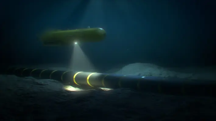
Nauticus Robotics, a developer of autonomous robots using artificial intelligence (AI) for data collection and intervention services, has been awarded a US$2.7mn contract extension with Leidos Holdings.
The extension allows for the continued development of Aquanaut-derivative in preparation for customer adoption decisions and government opportunities expected this year.
The subsea platform is an unmanned underwater vehicle (UAV) with advanced AI and sensing capabilities. It can perform a growing number of jobs without posing a hazard to human divers. The programme has now received US$14.5mn from Leidos since 2022 and the technology is expected to underpin major future opportunities.
Like the Aquanaut, the derivative robot features technology to support security activities and is advancing to complete more challenging missions. The award allows further autonomous behaviour and operational capability enhancements to toolkit, Nauticus’ proprietary software package developed to enable an ecosystem of autonomous actions for subsea vehicles and services as the foundation for this work.
Nicolaus Radford, founder and CEO of Nauticus, commented, "I am very proud of our team's performance resulting in this follow on award, further cementing our partnership with Leidos. This very important work combines great attributes from each company to deploy a truly novel subsea capability."
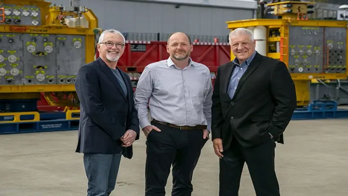
Subsea intervention technology specialist, Interventek, has agreed to supply a complete set of 20,000psi open-water well intervention shear and seal values to Trendsetter Engineering Inc.
The agreement allows Trendsetter exclusive global rights to deploy the 5-1/8” open-water valves for the next five years, with the first set to be delivered later this year.
The 20K Revolution valves are designed as a compact, modular addition for lightweight subsea intervention systems. They will provide the safety-critical well control function within Trendsetter’s new 20K Trident Subsea Intervention System, which is scheduled for the first field operations on a high pressure, high temperature (HPHT) subsea completion and intervention campaign in the Gulf of Mexico.
Interventek has previously supplied Trendsetter with serval 15,000psi Open-Water Revolution Valves, which were successfully deployed on multiple campaigns using its 15k Trident Intervention Systems.
Tony Kitchener, Sales and Marketing Director at Interventek, said, “Our new 20k Open Water Revolution Valves is leading the way in HPHT subsea well intervention safety. Qualified to rigorous API-17G and API 17TR8 standards, the valve maintains the superior cutting and resilient sealing capability that our unique technology is known for, delivering a future-proof solution for today’s operators.
“Our Revolution design is flexible and scalable so, with Trendsetter’s valuable and long-standing collaboration, it was natural for us to push ahead together to deliver the world’s first open-water HPHT intervention solution.”
Mike Cargol, Vice President of Services at Trendsetter, commented, “Interventek’s compact and high-performing Revolution valve is the ideal choice for our range of lightweight and modular Trident intervention systems. This technology is the key to achieving a reliable HPHT solution with around a 60% size and weight saving compared to other offerings.
“The result is a robust system which can be reconfigured to support hydraulic, riserless or open-water risered interventions and mobilised quickly on a broad range of vessels with minimal modifications. The bottom line for the operator is enhanced safety, rapid responses, increased operational efficiency and reduced costs.”
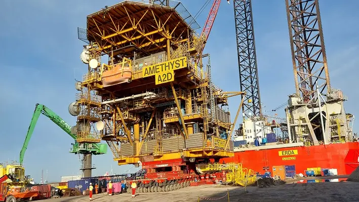
Perenco and Petrodec, a decommissioning services specialist, has announced that the A2D platform topside – located in the Amethyst Field, UKCS – has been safely removed for final dismantling.
The operation was successfully conducted using Petrodec’s patented ‘skidding’ technique deployed by its dedicated jack-up the ‘ERDA’ in the southern North Sea. With a weight of 1,179 tons, this was the heaviest Amethyst topside to have been removed so far.
The news follows the Hydrocarbon Safe (HCS) Campaign on all platforms and brine flushing of intra-field and export pipelines, the plug and abandon of all platform wells, and the removal of C1D, B1D and A2D topsides with a combined total topsides weight of 2,900 tons. The final operations to remove the topsides and four steel jackets of platform A1D are scheduled from January 2024.
The Amethyst field was one of the later-life assets acquired by Perenco from BP in 2012 as part a package of SNS assets. Perenco subsequently consolidated its position to 100% on Amethyst by acquiring the participating interests of Centrica and Murphy Oil in licences P.005, P.030, P.050 and P.133. Amethyst consisted of four conventional fixed jacket wellhead structures with helipads and cranes installed.
The platforms A1D, A2D, B1D and C1D had six or nine slots, and six or seven producing wells. The field stopped producing in 2020, following which Perenco UK started the application for decommissioning operations in collaboration with Petrodec.
Rainier Verhulst, Petrodec’s General Manager, said, “The successful and safe skidding operation to remove the heaviest topside to date exemplifies Petrodec’s technical ingenuity as a decommissioning specialist, bringing together the technical expertise of a contractor and the reliability of a decommissioning operator.
“It also clearly highlights Perenco’s integrated approach to late-life assets, first extending the production lifespan of assets by operational efficiencies and investment, then developing innovative and fit-for-purpose solutions to safely decommission the facilities. I would like to thank all of those involved.”
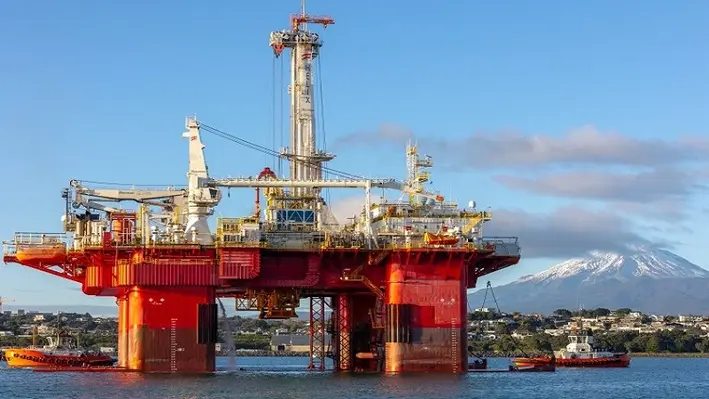
Brazil has posed itself as one of the key drivers in the Latin American market that is driving the region's growth in the international oil and gas game. A net oil importer until 2014, Brazil has become the top producer in Latin America in 2016, and since then has enjoyed uncontested leadership in the region. While this represents a great opportunity for the region’s oil and gas sector, from the operators to service providers supporting them, there is a looming decommissioning wave on the horizon.
The global oil market has been witness to many ups and downs since the advent of the Covid-19 pandemic. Far from stability, it has weathered a persistent conflict in eastern Europe; re-emergence of Covid-19 in China; major, consecutive price cuts by OPEC+ nations, and a global uptake on renewable activity. The IEA, however, has indicated that oil demand would remain steady until it reaches a peak in the mid-2030’s at 103mn bpd before beginning to plateau. It predicted that despite the global energy mix changing to accommodate the surgence of renewable practices coming to the forefront, fossil fuels will still hold a 60% share within the energy game until at least mid-century.
The Ministry of Mines and Energy (MME) in Brazil has big plans on drawing investment to the country's petroleum sector. It will be focusing on the various ways to drive exploration in frontier areas and call for investments in mature, as well as marginal, economic fields. Owing to these ambitious goals, there is a dual opportunity for both greenfield development and production enhancement through well intervention.
Besides the active role of Petrobras on advancing the country’s oil and gas industry, new players are also emerging as the state-owned Brazilian Petroleum Company has been passing on its mature assets to several entities from BW Energy to Trident over the last few years. Petrobras itself has plans to decommission 26 of its floating platforms, with the P-32 asset scheduled to begin the process this year.
On the other hand, high marketed utilisation rates of offshore rigs, especially in Latin America following the eastern European conflict, led to a supply chain gridlock. While many operators are considering collaboration between companies in order to use the same vessel for their respective assets, logistically, that process could also present challenges.
Another challenge in the well intervention industry lies in tackling the high costs involved in the process. This has resulted in the popularity of a slightly more fresh-faced method – riserless light well intervention (RLWI). Used instead of heavier vessels, this has the potential to significantly reduce cost of operations and minimise environmental impact – an increasingly pressing concern for operators.
Well-Safe Solutions, a contractor which offers the complete package for well decommissioning, has unveiled a D300 saturation diving system aboard the Well-Safe Guardian rig.
The addition, makes the semi-submersible the only one of its type in the North Sea with this capability.
The custom-built dive spread, with capacity for up to 15 persons, enables safe access to legacy subsea wellhead and christmas tree systems from the 1970s onwards which were originally designed for diver intervention.
“With 48% of overall decommissioning expenditure in 2022 focused on well abandonment alone, Well-Safe Solutions has identified a clear market in mature basins such as the UK Continental Shelf for this technology,” commented Phil Milton, Chief Executive Officer at Well-Safe Solutions.
“The dive spread system installed on the Well-Safe Guardian is a cost-effective, flexible alternative to the industry standard, which typically sees a light well intervention vessel (LWIV) used to plug and lubricate the well before completing decommissioning operations with a standard semi-submersible mobile offshore drilling unit (MODU).
“Our ‘single asset solution’ offers an alternative to the conventional approach and does not require multiple vessel mobilisations and demobilisations. This results in lower operating costs, minimises the risk of weather-related disruption and boosts overall project efficiency.”
Milton explained that comparative analysis studies have demonstrated the value this solution can bring to the wider decommissioning industry as it streamlines processes and costs alike.
“Our data shows that the use of the Well-Safe Guardian to plug and abandon (P&A) five wells over three fields in the North Sea generates a 15% total cost reduction and is 44 days quicker than using a LWIV and MODU pairing,” continued Milton. “We are delighted to be able to bring this solution to market as part of our vision to become the industry’s well decommissioning partner of choice.”
The manufacture, transport and fitment of the dive spread was carried out at Burntisland, Rosyth and Methil ports on the east coast of Scotland.
The system is designed to enable diving operations to be carried out in support of well decommissioning. Typical operations supported include cleaning, deconstruction, barrier testing, manual tree cap removal, reconfiguration of hydraulic controls and flowline removal.
Following further systems integration and testing, the Well-Safe Guardian will mobilise early summer 2023, returning to the Buchan field operated by Repsol Sinopec Resources UK to plug and abandon nine wells using the saturation dive system, the Trident well intervention system and the blow out preventer, realising the full potential of this single asset solution. UK-based RockSalt Subsea will support Well-Safe Solutions with diving services and personnel during all saturated diving operations from the Well-Safe Guardian.
David Whitehouse, Chief Executive Officer of Offshore Energies UK, added, “The UK offshore energy industry has a long history of developing world-class solutions to the challenges it has faced and continues to face.
“This latest development and adoption of technology on the Well-Safe Guardian from Well-Safe Solutions shows an absolute commitment to drive forward innovation to improve efficiency for the plug and abandonment of wells. These efficiency improvements will also have a positive impact on safety and environmental performance.
“After 50 years of operating in the North Sea, this level of dedication to UK innovation is important as we continue to meet the UK’s energy needs using home grown jobs, skills and technology.”
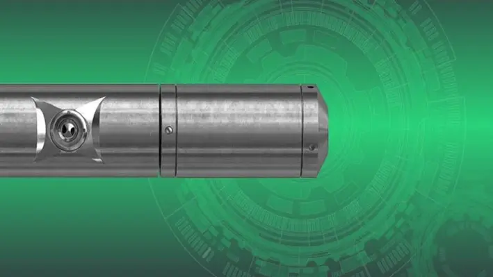
Welltec has announced its Puncher 218 technology has won at the Hart Energy’s E&P 2023 Special Meritorious Awards for Engineering Innovation (MEA). The MEA programme recognises new products and technologies which demonstrate innovation through their concept, design, and application.
“This award is a fantastic acknowledgment of the advances we continue to make within our intervention technologies,” said Alex Nicodimou, Welltec VP for Sales & Marketing.
“We are constantly improving and evolving our portfolio, while also developing new services and new service sizes as in this particular case. The focus is always to help our clients and continue to make operations more efficient, more controllable, and more reliable through technology.”
The Welltec Puncher 218 provides an efficient, e-line conveyed, non-explosive method for equalising pressures between tubular strings. Its innovative design is ideal for extended reach and going beyond narrow internal diameter restrictions, and is currently the slimmest non-explosive puncher capable of creating multiple perforations on a single run in the market.
Jordan Blum, Editorial Director at Hart Energy, said, “Technology has clearly been at the forefront as the industry has challenged the frontiers of exploration, drilling, and production. We applaud Welltec’s commitment to technological progress in the upstream area, and we congratulate them on receipt of this award.”

TotalEnergies EP Nederland has appointed ABL Group, an independent energy and marine consultancy, as marine warranty surveyor for the decommissioning operations of the L7 field in the Dutch sector of the North Sea.
The L7 Restitution Project includes the decommissioning of nine jackets and ten topside modules, including bridge structures from the L7 field. The total weight of the installations is approximately 17,500 tonnes.
ABL will provide marine warranty survey services for the preparations, lifted removals, transportation and relocation to the onshore dismantling yard located in Norway. ABL will also conduct suitability surveys of all the marine units that will be utilised for the project.
Ashley Perrett, ABL’s Country Manager in Scotland, commented, “ABL Group has a long history in the oil and gas sector and vast experience with the challenges and important considerations that can impact decommissioning work. We are delighted to be partnering with TotalEnergies EP Nederland on the L7 project as part of our growing portfolio of work in this area.”
Planning work has already commenced, and offshore operations will occur throughout 2023 and 2024. The installations will be removed using a floating sheerleg crane that will transfer cargo to a barge in sheltered waters near Den Helder, Holland, for onward transit to the dismantling yard located in Vats, Norway. AF Offshore Decom will manage the removal and recycling of the installations.
“Decommissioning of oil and gas fields is a complex task. As a non-productive cost, we fully appreciate the importance of identifying the correct solution to ensure cost-efficiency without compromising safety and quality,” commented Nicholas Kaczynski, ABL Group’s Project Manager for the L7 decommissioning project.
ABB, a technology leader in electrification and automation, has highlighted how its emissions monitoring technology is now employed to identify and monitor orphan wells in the United States.
With the help of ABB technology, organisations such as The Well Done Foundation, the nonprofit organisation that works to plug orphan oil and gas wells in the country, can detect leaking wells and, once the wells are capped, continue to monitor the sites to ensure they no longer emit harmful greenhouse gases.
The United States Environmental Protection Agency estimates that methane emissions from over two million inactive, unplugged wells, of which orphan wells are a subset, range from a CO2 equivalent of 7 to 20 million metric tons per year (approximately the emissions of two to five million cars). Methane has more than 80 times the warming power of carbon dioxide over the first 20 years after it reaches the atmosphere, according to the Environment Defense Fund.
“It is extremely rewarding to see our technologies employed in the endeavor of fixing such a pressing environmental problem. We remain focused on accelerating the pace of environmental programmes that reduce emissions, especially in the oil and gas industry. Our work on this initiative is a great example of how technology can benefit the environment and help countries achieve their sustainability goals,” sayid Jacques Mulbert, Division President, ABB Measurement & Analytics.
Together with channel partner Winn-Marion, ABB worked to create a comprehensive approach that enables the identification, on-site qualification, and monitoring of orphan wells.
Initially, ABB’s gas leak detection system is used to find the orphan wells. Depending on their location, the high sensitivity analysers using OA-ICOS technology are transported by vehicle (using ABB Ability MobileGuard), drone (HoverGuard), or backpack (MicroGuard) to the site. The system can detect methane emissions down to one part per billion (ppb).
Once on-site, it measures methane concentration and flow with a measuring range as low as 180kg/h. The flow from the thermal mass is logged and visualised on ABB’s gas flow computers, the control devices known in the industry for their extreme accuracy and reliability. In the post-plugging phase, methane emissions continue to be monitored.
Page 74 of 122